3.11. Measurements
The tool allows you to make linear and polygonal linear measurements of distances in an image.
 | The measurement accuracy is up to one screen pixel. As a screen pixel is smaller than a source image pixel, the true linear measurement accuracy is up to one source image pixel. Errors may also occur in density measurements. The most accurate measurements are performed with bilinear interpolation (see Section 2.5). |
3.11.1 Ruler
To make linear measurements:
-
Activate the
 Ruler tool by clicking the left/right/middle mouse button. To continue
work with this tool, use the button with which the tool was activated. To learn more
about tool control, see Section 1.14.
Ruler tool by clicking the left/right/middle mouse button. To continue
work with this tool, use the button with which the tool was activated. To learn more
about tool control, see Section 1.14.
-
You can measure the distance in two ways:
-
Mark the first point by clicking the mouse button. Drag the cursor over the screen. The distance from the first point to the current point will be displayed beside the line. To fix the current point, click the mouse button.
-
Click on the mouse button at the starting point and move the cursor to the endpoint while holding the mouse button. The distance from the first point to the current point will be displayed beside the line. To fix the endpoint, release the mouse button.
-
-
To cancel an incomplete measurement, press Esc.
To move the ruler border:
-
Locate the cursor on the point to be moved so that it would look like this
 .
.
-
Drag the point, holding the left mouse button.
-
Release the left mouse button.
To delete a ruler:
-
Locate the cursor on the line to be deleted so that it would look like this
.
-
Press the Delete key on the keyboard or right-click the mouse and select the Remove ruler command.
This tool is also available from the model context menu and from the Volume main menu item. Activation is only possible with the left mouse button.
3.11.2 Polygonal Ruler
To perform plygonal linear measurement:
-
Activate the
 Polygonal ruler tool by clicking the left/right/middle mouse button.
To continue work with this tool, use the button with which the tool was activated. To
learn more about tool control, see Section 1.14.
Polygonal ruler tool by clicking the left/right/middle mouse button.
To continue work with this tool, use the button with which the tool was activated. To
learn more about tool control, see Section 1.14.
-
Mark the first point on the toolbar by clicking the mouse button.
-
Drag the cursor over the screen. The distance from the first point to the current point will be displayed beside the line.
-
To fix the current point, click the mouse button.
-
Repeat Steps 3 and 4 until the last but one point is fixed.
-
Fix the last point by double-clicking the mouse.
-
To cancel an incomplete measurement, press Esc.
To move the linear measurement point:
-
Locate the cursor on the point to be moved so that it would look like this
.
-
Drag the point, holding the left mouse button.
-
Release the left mouse button.
To delete a point:
-
Locate the cursor on the point to be deleted so that it would look like this
.
-
Right-click the mouse and select the Remove point command.
To insert a point:
-
Locate the cursor on the ruler where you want to insert a point so that it would look like this
.
-
Right-click the mouse and select the Insert point command.
To resume a completed polygonal linear measurement:
-
Locate the cursor on the point from which you want to continue the measurement, so that it would look as follows:
.
-
Right-click the mouse and select the Resume ruler command.
-
Perform the polygonal linear measurement.
To delete a completed polygonal linear measurement:
-
Locate the cursor on the measurement to be deleted so that it would look like this
.
-
Press the Delete key on the keyboard or right-click the mouse and select the Remove ruler command.
This tool is also available from the model context menu and from the Volume main menu item. Activation is only possible with the left mouse button.
3.11.3 Surface ruler
____________________________________________________________________________________________
Functionality is available in the Pro edition
____________________________________________________________________________________________
A distance on the surface of a visible volume may only be measured in the Volume reconstruction tab.
To measure a distance on the surface of a visible volume or a surface, proceed as follows:
-
Activate the
 Surface ruler tool by clicking the left/right/middle mouse button.
To continue work with this tool, use the button with which the tool was activated. To
learn more about tool control, see Section 1.14.
Surface ruler tool by clicking the left/right/middle mouse button.
To continue work with this tool, use the button with which the tool was activated. To
learn more about tool control, see Section 1.14.
-
Mark the first point on the toolbar by clicking the mouse button.

There may be a delay before the first point is displayed as it takes some time to bind the first point to the segmented structure. -
Drag the cursor over the screen. The next point number is displayed next to the cursor.
-
To fix the current point, click the mouse button.
-
Repeat Steps 3 and 4 until the last but one point is fixed.
-
Fix the last point by double-clicking the mouse.
The line reflecting the change is built along the shortest path between the points on the surface of only one segmented structure. The distance is measured on the surface of the segmented structure where the first point is placed.
Selecting a segmented structure to place the first point is based on the Point projection setting of the Render settings tool. For details on render setting tool management, see Section 3.14.
If more than one segmented structure is created in the project that satisfies the criterion for placing the first point, the point is placed on the structure located in the foreground. You can measure the distance on the surface of the structure in the background in several ways:
-
rotate the volume model so that there are no other structures in front of the selected structure;
-
turn off the visibility of the structure in the foreground;
-
change the opacity value of the foreground structure.
If the path cannot be built, an Unable to find the path message pops up, and the last path that was successfully built is restored. The measurement path is highlighted when you hover over it, and the numbers of the points are shown.
| | It is impossible to measure a distance on the surface of a imported or copied surface. |
Imported and copied surfaces are structures without a 3D model. If the user attempts to make a measurement on the surface of an imported/copied surface, a warning message will pop up.
If a measurement path is built on the surface of a segmented structure (base volume, or surface) that is invisible, a warning will pop up if a user attempts to edit the path.
In the merged series opened in the Volume reconstruction tab, the distance on the surface of the segmented structure is measured in the same way. The first measurement point along the surface of the structure is placed on the layer that is in the foreground. To measure the distance on the surface of the structure located on the background layer, decrease transparency of the foreground layers.
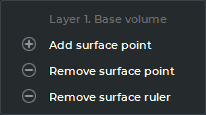
In addition to commands, the context menu of the Surface ruler (Fig. 3.10) contains information concerning the layer and the segmented structure on which the measurement path to be edited was built. To open the context menu for the tool, right-click on a point, the path or the text describing the path length.
To move a point of a measurement path, proceed as follows:
-
Locate the cursor on the point to be moved so that it would look like this
.
-
Drag the point, holding the left mouse button or the button, with which the tool is activated.
To add a point in order to proceed with building a measurement path, proceed as follows:
-
Locate the cursor over the first or the end point of the measurement path so that it would look like this
.
-
Right-click the mouse and on the context menu select the Add surface point command.
-
Proceed with building the measurement path.
To add a new point to a path between two existing points, proceed as follows:
-
Hover the cursor over the place on the path where you want to add a point so that it would look like this
.
-
Right-click the mouse and on the context menu select the Insert surface point command.
-
Drag the cursor over the screen. To fix the new point, click the mouse button.
To delete a point:
-
Locate the cursor on the point to be deleted so that it would look like this
.
-
Right-click the mouse and on the context menu select the Remove surface point command.
The deletion of a single point does not lead to rebuilding the measurement path completely. Only the segment between the two neighboring points will be rebuilt.
To rebuild the edited measurement path, hover the cursor over the path or the text describing the
path length so that it would look like this . Right-click and select the Rebuild the entire
ruler option on the context menu.
There are several ways to delete a measurement:
-
To delete an incomplete measurement, press Esc.
-
To delete a measurement path, hover the cursor over the path, a point, or the text describing the path length so that it would look like this
. Press the Delete key on
the keyboard or right-click and select the Remove surface ruler option on the context
menu.
-
To delete all measurements, click the Delete all Measurements
 button on the
toolbar. In the dialog box that appears, Click YES to delete or NO to cancel. If you
want the DICOM Viewer to always delete annotations and measurements without this
confirmation, check the box Don‘t show this dialog again and click YES. If you want
the DICOM Viewer to show the confirmation dialog, check the box Ask before deleting
all annotations and measurements (see Section 16.7.1).
button on the
toolbar. In the dialog box that appears, Click YES to delete or NO to cancel. If you
want the DICOM Viewer to always delete annotations and measurements without this
confirmation, check the box Don‘t show this dialog again and click YES. If you want
the DICOM Viewer to show the confirmation dialog, check the box Ask before deleting
all annotations and measurements (see Section 16.7.1).
The Surface ruler tool is also available from the model context menu and from the Volume main menu item. Activation is only possible with the left mouse button.
3.11.4 3D Angle
To measure an angle on the model:
-
Activate the 3D Angle
 tool by clicking the left/right/middle mouse button. To
continue work with this tool, use the button with which the tool was activated. To learn
more about tool control, see Section 1.14.
tool by clicking the left/right/middle mouse button. To
continue work with this tool, use the button with which the tool was activated. To learn
more about tool control, see Section 1.14.
-
Make two points on the model clicking the mouse button. The second point is the angle apex.
-
Move the cursor over the screen to set the other side of the angle.
-
Click the mouse button to fix the second side of the angle.
-
To cancel an incomplete measurement, press Esc.
To move the 3D angle point:
-
Locate the cursor on the point to be moved so that it would look like this
.
-
Drag the point, holding the left mouse button.
To remove the 3D angle:
-
Locate the cursor on the line of the 3D angle to be deleted so that it would look like this
.
-
Press the Delete key on the keyboard or right-click the mouse and select the Remove 3D angle command.
This tool is also available from the model context menu and from the Volume main menu item. Activation is only possible with the left mouse button.
3.11.5 Arrow Tool
The Arrow tool is used in the Volume reconstruction tab for creating graphic annotations in the shape of arrows tied to certain points of a 3D model.
To create an arrow directed at a certain point of a 3D model, proceed as follows:
-
Activate the Arrow tool
 by clicking the left/right/middle mouse button. To
continue work with this tool, use the button with which the tool was activated. To learn
more about tool control, see Section 1.14.
by clicking the left/right/middle mouse button. To
continue work with this tool, use the button with which the tool was activated. To learn
more about tool control, see Section 1.14.
-
There are two ways to draw an arrow on a 3D model:
-
Press the mouse button at the point where the arrow tip is to be placed and, while holding the mouse button, move the cursor to the opposite end of the arrow. To fix the point, release the mouse button.
-
Click the mouse button at the point where the arrow tip is to be placed. Click the mouse button again where the opposite end of the arrow should be placed.
-
-
To cancel an incomplete creation, press Esc.
The arrow directed at a visible point on a 3D model is shown completely (see the red arrow in Fig. 3.11). If the arrow is hidden behind the model, it is collapsed (see the green markers in Fig. 3.11).
To move the tip or the end of an arrow, proceed as follows:
-
Locate the cursor on the point to be moved so that it takes the following shape
.
-
Holding the left mouse button or the button with which the tool was activated, drag the point to the correct place.
To delete an arrow, proceed as follows:
-
Locate the cursor on the arrow to be deleted so that the cursor takes the following shape
.
-
Press the Delete key on the keyboard or right-click the mouse and select the Remove arrow command.
To customize the tool parameters, locate the cursor on the arrow so that it takes the
following shape . Right-click the mouse and select Options... from the context
menu.
In the Arrow options dialog box that pops up, specify the color and the line weight for the arrow. Add a short description in the Text field and specify the font size. If the Set as default box is checked, the provided settings for the color, line weight and font size will be applied by default to all the new arrows built. Click OK to apply the settings or CANCEL to cancel.
This tool is also available from the model context menu and from the Volume main menu item. Activation is only possible with the left mouse button.
3.11.6 Customizing the Text Size for Measuring Tools
To change the text size for a measurement that has already been displayed, right-click on the point, line or text referring to the measurement result. On the context menu that pops up, select the Options...
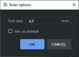
In the dialog box (Fig. 3.12), set the text size in millimeters. The minimum size is 1. If you want the new settings to be applied to all the new measurements by default, check the Set as default box.
Click OK to apply the settings or CANCEL to cancel.