6.2. The Mask
6.2.1 Creating a new structure and mask
____________________________________________________________________________________________
Functionality is available in the Pro edition
____________________________________________________________________________________________
-
Click the Add a new structure
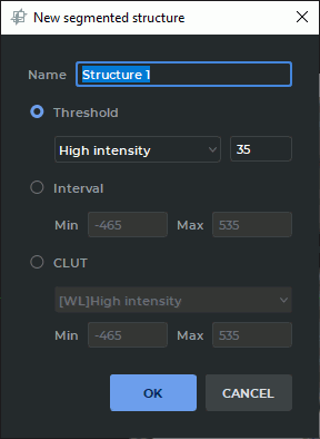
 button. The dialog shown in Fig. 6.4 appears.
-
Enter the name of the new structure in the Name field. By default, the name of the structure is automatically generated by the <Structure X> template, where X is the counter with the increment of one point. The first value is 1.
-
Set the tissue density values for the mask. You can do it in one of the three ways:
-
using the Threshold mode. In this mode the mask is set for the tissue whose density is greater or less than the specified threshold value. To set the mask for the tissue with a density less than the threshold, select the Low intensity setting, and vice versa. Set the threshold;
-
using the Interval mode. In this mode the mask is set for the tissue whose density is in the range from minimum to maximum;
-
using color tables. In this mode the mask is set for the tissue displayed for the selected color table.
-
-
Click OK to create a new structure and mask or CANCEL to cancel.
6.2.2 Changing the structure mask using CLUTs
____________________________________________________________________________________________
Functionality is available in the Pro edition
____________________________________________________________________________________________
You can change the mask of the current structure in several ways:
-
Using the Adjust W/L tool:
-
Select the target structure on the panel of segmented structures.
-
Click the Adjust W/L
 button on the toolbar.
-
Change the window width and level for the editing mask (see Section 2.17). The green editing mask changes in real time in the MPR window.
-
-
Selecting the color table from the dropdown list (see Section 2.23.1) or with the Custom W/L
 tool (see Section 2.17).
-
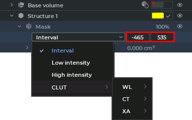
For the properties tree on the Segmented structure panel (Figure 6.5):
-
Unfold the list of the segmented structure properties.
-
In the drop-down list, select the editing mask mode or the color table you need:
-
The High intensity and Low intensity mode provides the editing mask for tissues whose density is above or below the threshold value.
-
The Interval mode provides the editing mask for tissues whose density is within the set value range.
-
The CLUT mode provides the editing mask for the tissues displayed for the chosen color table.
-
-
To change the interval or the density threshold, click with the left mouse button on the values (see the red box in Figure 6.5). Provide the values you need and press Enter key on the keyboard.
The editing mask parameters (the color table, the intensity threshold value and the interval) are changed for each segmented structure separately. The color table type and the editing mask mode for the segmented structure selected is shown on the visualization setup panel.
-
-
For the Volume Reconstruction window only: using the Set mask tool (see Section 6.2.4).
You can change the editing mask visibility for the current structure using the editing mask setup panel (see Section 6.2.3).
6.2.3 The Editing mask
____________________________________________________________________________________________
Functionality is available in the Pro edition
____________________________________________________________________________________________
The editing mask is a pattern beyond which the structure mask is not visible.
The editing mask is not visible in the volume reconstruction window, and it is displayed in green in the MPR window. If necessary, the editing mask can be inverted. In this case, the tissues not under the editing mask are displayed in green. To invert the editing mask, set the flag Invert edit mask on MPR (see Section 16.7.3).
The editing mask can be changed at any time (see Section 6.2.2). If the editing mask is reduced
and the structure goes beyond the editing mask, then this part of the structure becomes invisible and
is not taken into account in the calculations. However, it is not removed and when the editing mask is
increased, it becomes visible again.
You can change the editing mask visibility for the current structure using the editing mask setup panel (Fig. 6.6). The panel is placed at the bottom of the segmented structures panel and is only available in the MPR reconstruction tab.
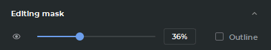
There are two ways to change the visibility of the editing mask:
-
move the slider or roll the mouse wheel while the cursor is placed on the slider;
-
enter the opacity value in the field on the right-hand side of the slider.
The editing mask opacity value is expressed as a percentage.
To see the outline of the editing mask, check the Outline box.
To conceal the editing mask, click the Hide mask  button on the editing mask setup panel.
To display the editing mask, click the Show mask
button on the editing mask setup panel.
To display the editing mask, click the Show mask  button.
The Hide mask button is unavailable if at least one tool for segmentation or volume
editing has been activated.
To minimize the editing mask setup panel, click the Hide  button. To display the hidden
panel, click the Show
button. To display the hidden
panel, click the Show  button.
6.2.4 Set Mask Tool
____________________________________________________________________________________________
Functionality is available in the Pro edition
____________________________________________________________________________________________
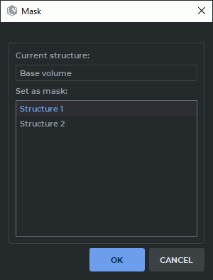
The tool is only available for the Volume reconstruction tab. To set a structure as a mask for another structure or base volume, proceed as follows:
-
On the list of structures, select the structure (base volume) for which you want to change the mask.
-
Click on the Set Mask
 button. The dialog shown in Fig. 6.7 will be displayed.
-
On the list of structures, select the structure (base volume) you want to set as the mask.
-
Click OK to confirm or CANCEL to cancel the action.