6.8. Changing the structure mask with segmentation tools
____________________________________________________________________________________________
Functionality is available in the Pro edition
____________________________________________________________________________________________
When working with segmented structures, pay attention to which structure or volume is selected.
All the editing operations are performed with a selected visible structure mask or volume. If the
visibility button  (Fig. 6.22) hides the visibility of mask and surface for this structure editing is
not possible because the cutting tools (Segmentation from point by mask, Region growing and
Vessel tree segmentation) are deactivated.
(Fig. 6.22) hides the visibility of mask and surface for this structure editing is
not possible because the cutting tools (Segmentation from point by mask, Region growing and
Vessel tree segmentation) are deactivated.
Invisible structures can be edited with smart volume editing tools, such as Grow (dilation), Shrink (erosion), Remove noise (opening), Remove holes (closing) (for details see Section 3.8.7), as well as Union, Subtract, Subtract dilated, and Intersect tools see Section 6.9.
In this case, the dialog box is displayed: The target structure is hidden. Are you sure you want to apply the operation to it? Click Yes to proceed or No to cancel.
If the volume model is open (see Section 5.21), then the created structure appears simultaneously
on the model. This causes additional load on the processor. If you want to reduce the load, click the
arrow on the Growing Region  button and uncheck the Interactive 3D Update item. After
this, the structure on the volume model will be updated after the next structure creation phase is
completed.
button and uncheck the Interactive 3D Update item. After
this, the structure on the volume model will be updated after the next structure creation phase is
completed.
If a base volume or mask of segmented structure is edited, the respective surfaces are automatically rebuilt.
To edit a structure mask, use specialized tools (described below) and volume editing tools:
-
Polygon Cut (see Section 3.8.1);
-
Inverse Polygon Cut (see Section 3.8.2);
-
Delete Area (see Section 3.8.3);
-
Delete All Areas except Selected Area (see Section 3.8.4);
-
Brush Cut (see Section 3.8.6);
-
Brush Restore (see Section 3.8.6). The use of the tool is possible only if a part of the structure is already created;
-
Contour segmentation (see Section 6.10);
-
Grow (dilation) (see Section 3.8.7);
-
Srink (erosion) (see Section 3.8.7);
-
Remove noise (opening) (see Section 3.8.7);
-
Remove holes (closing) (see Section 3.8.7);
-
Multi-segment growing (see Section 3.8.7);
-
Fill (see Section 3.8.7).
-
Cut Invisible Volume (see Section 6.9);
-
Vessels Tree Segmentation (see Section 6.8.4);
-
Segmented structures regions growing (see Section 6.8.7);
-
Union (see Section 6.9);
-
Subtract (see Section 6.9);
-
Subtract dilated (see Section 6.9);
-
Intersect (see Section 6.9).
6.8.1 Tools for automatic segmented structure mask filling
____________________________________________________________________________________________
Functionality is available in the Pro edition
____________________________________________________________________________________________
The Segmentation from point by mask tool allows you to create a structure mask for a bound area. It is necessary that the structure mask for this area does not touch the structure masks of the neighboring areas. To create a structure mask:
-
Activate the Segmentation from point by mask
 tool by clicking the
left/right/middle mouse button. To continue work with this tool, use the button with
which the tool was activated. To learn more about tool control, see Section 1.14.
tool by clicking the
left/right/middle mouse button. To continue work with this tool, use the button with
which the tool was activated. To learn more about tool control, see Section 1.14.
-
Click on the bound area.
-
If the structure mask was created for a larger area than required, undo the action by clicking the Undo
 button. Change the window width and level so that the editing
mask for this area is not in contact with the masks of the neighboring areas and create
the mask again.
button. Change the window width and level so that the editing
mask for this area is not in contact with the masks of the neighboring areas and create
the mask again.
If it is impossible to get a bound area completely separated from other tissues, then if you use the
tool Segmentation from point by mask, there will be leaks (segmentation beyond the required
area). To create a segment quickly and with minimal leaks, use the Region growing
tool:
-
Activate the Region growing tool by clicking the left/right/middle mouse button. To continue work with this tool, use the button with which the tool was activated. To learn more about tool control, see Section 1.14. The tool modes are described in Section 6.8.3.
-
Select the point on the editing mask roughly in the center of the region you want to segment.
-
Move the cursor in any direction, holding the mouse button. The structure mask will grow. The growth occurs faster in those directions in which the curvature of the surface is less (in thin sections the growth is slower to avoid leaks). The direction of the cursor movement does not matter, the distance from the starting point of the movement is important. When the cursor moves in the opposite direction, the structure mask does not decrease.
-
If the structure is completely created or if any further growth leads to leaks, stop the growing process by releasing the left mouse button.
-
If necessary, repeat the growing process for the tissue not yet segmented.
-
To undo an action, click the Undo
button, to redo the canceled action click the
Redo  . However, keep in mind that the tool will operate at regular intervals, so
with a single click on the Undo button, you can only delete that part of the structure
mask that was added as part of the previous execution or a series thereof, but not along.
. However, keep in mind that the tool will operate at regular intervals, so
with a single click on the Undo button, you can only delete that part of the structure
mask that was added as part of the previous execution or a series thereof, but not along.
6.8.2 Brush restore tool
____________________________________________________________________________________________
Functionality is available in the Pro edition
____________________________________________________________________________________________
To fill out the structure mask using the Brush restore tool:
-
Activate the Brush restore
 tool by clicking the left/right/middle mouse button.
To continue work with this tool, use the button with which the tool was activated. To
learn more about tool control, see Section 1.14.
tool by clicking the left/right/middle mouse button.
To continue work with this tool, use the button with which the tool was activated. To
learn more about tool control, see Section 1.14.
-
Set the tool diameter. To do this, move the mouse cursor up and down, holding the Alt key (or the Option key for macOS) on the keyboard.
-
Move the mouse cursor to the area for which you want to create a structure mask.
-
Click the mouse button. The tissues that are under the editing mask and inside the sphere will be added to the mask. The tissue color changes to the one set for the structure.
-
To undo the action, click the Undo
button, to repeat the canceled action, click
the Redo button.
-
To add a large area to the structure, move the Brush restore
tool, holding the
mouse button. However, keep in mind that the tool will operate at regular intervals, so
with a single click on the Undo button you can only delete that part of the structure
mask that was added as part of the previous execution or a series thereof, but not along.
-
To remove a part of the tissue from the structure, activate the Brush cut
 tool.
The tool works in the same way as to the Brush restore tool, but unlike the Brush
restore tool, it removes the tissue from the structure.
tool.
The tool works in the same way as to the Brush restore tool, but unlike the Brush
restore tool, it removes the tissue from the structure.
-
To disable or enable the editing mask, click the visibility button
on the Editing
mask panel.
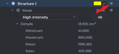
In the Volume Reconstruction window, the tool is used for structure mask growth regardless of the editing mask. To grow a structure mask, use Restore by mask tool. Note that to fill the structure mask, you need some volume (base volume or the structure) to be visible. The visibility button (see the red arrow in Fig. 6.23) turn on visibility of all masks and surfaces for this structure. Otherwise, you won’t be able to grow another mask.
6.8.3 Region growing tool
____________________________________________________________________________________________
Functionality is available in the Pro edition
____________________________________________________________________________________________
When using the Brush restore tool, there may be leaks (structure mask beyond the required
area). The Region growing tool takes into account the shape and density of the segmented
areas and allows users to minimize leaks. The tool has two modes: EDT Method and Level Set
Method. To switch the mode, click the arrow on the button and select the desired mode. The
current mode is marked by the flag.
The EDT Method mode allows you to create a structure mask in the editing mask space. To create a structure mask:
-
Activate the Region growing
tool in the EDT Method mode by clicking the
left/right/middle mouse button. To continue work with this tool, use the button with
which the tool was activated. To learn more about tool control, see Section 1.14.
-
Select the point on the editing mask roughly in the center of the region you want to segment.
-
Move the cursor in any direction, holding the mouse button. The structure mask will grow. The growth occurs faster in those directions in which the curvature of the surface is less (in thin sections the growth is slower to avoid leaks). The direction of the cursor movement does not matter, the distance from the starting point of the movement is important. When the cursor moves in the opposite direction, the structure does not decrease.
-
If the structure mask is completely created or if any further growth leads to leaks, stop the growing process by releasing the left mouse button.
-
If necessary, repeat the growing process for the tissue not yet segmented.
-
To undo an action, click the Undo
button, to redo the canceled action, click the
Redo button. However, keep in mind that the tool will operate at regular intervals,
so with a single click on the Undo button you can only delete that part of the structure
mask that was added as part of the previous execution or a series thereof, but not along.
If the Level Set Method is selected, the tool uses its own editing mask created according to a special algorithm. Hence, the created structure mask can go beyond the standard editing mask, and when you change the mask boundaries, it will be visible. To create a structure mask:
-
Activate the Region growing
tool in the Level Set Method mode by clicking
the left/right/middle mouse button. To continue work with this tool, use the button with
which the tool was activated. To learn more about tool control, see Section 1.14.
-
Select the point on the mask roughly in the center of the region you want to segment.
-
Press and hold the mouse button. A separate blue tool editing mask appears in the window in which you are working. If the mask is poorly visible against the background of the standard editing mask, reduce the opacity of the editing mask. To do this, reduce the opacity value in the Editing Mask panel (see Section 6.2.2).
-
Access the coverage of the tissues by the blue editing mask. The density of the tissues that are under the blue editing mask depends on the density under the cursor. If the blue editing mask is not built correctly, then release the left button, cancel the mask creation by clicking the Undo
button or deleting the mask; move the cursor to the tissue
section with the desired density, and repeat this step.
-
The red circle around the cursor shows the curvature of the areas that will be segmented (the smaller the diameter of the circle is, the greater curvature is allowable, that is, the thinner tissues will be segmented). To change the diameter of the circle, move the cursor up or down, pressing the Alt key (or the Option key for macOS) on the keyboard.
-
Move the cursor in any direction, holding the mouse button. The structure mask will grow under the blue editing mask. If the blue editing mask goes beyond the standard editing mask, the mask can be built beyond the standard editing mask, but it will be visible only within the standard editing mask.
-
If the structure mask is completely created or if any further growth leads to leaks, stop the growing process by releasing the mouse button.
-
If necessary, repeat the growing process for the tissue not yet segmented.
-
To undo an action, click the Undo
button, to redo the canceled action click the
Redo button. However, keep in mind that the tool will operate at regular intervals,
so with a single click on the Undo button you can only delete that part of the structure
mask that was added as part of the previous execution or a series thereof, but not along.
If the volume model is open (see Section 5.21), then the created structure appears simultaneously
on the model. This causes additional load on the processor. If you want to reduce the load, click the
arrow on the Growing Region button and uncheck the Interactive 3D Update item. After
this the structure on the volume model will be updated after the next structure creation phase is
completed. The visibility of the surface does not affects the ability to edit the structure
mask. The segmentation tools work if visibility for the structure and/or surface mask is
enabled.
6.8.4 Vessel tree segmentation tool
____________________________________________________________________________________________
Functionality is available in the Pro edition
____________________________________________________________________________________________
The tool is used for blood vessels segmentation.
Segmentation is performed only for the visible part of the structure (base volume). Before using the tool, delete the parts of the image you don‘t need with the help of cutting tools. For lung vessels you can use the lung vessels area selection tool. To do that, click on the arrow in the right-hand part of the Vessel tree segmentation button and choose Extract lung vessels area. It may take time. After the lung vessels area has been selected, a colour lookup table "[WL]High Intensity" is assigned. For details on CLUTs see Section 2.23.
 | The Extract lung vessels area tool works correctly only on studies with contrast. |
To perform segmentation:
-
Select the target structure (the base volume). The visibility
button turn on visibility
of structure mask.
-
Activate the Vessel tree segmentation
 tool by clicking the left/right/middle
mouse button. To continue work with this tool, use the button with which the tool was
activated. To learn more about tool control, see Section 1.14.
tool by clicking the left/right/middle
mouse button. To continue work with this tool, use the button with which the tool was
activated. To learn more about tool control, see Section 1.14.
-
Specify the following parameters in the dialog box:
-
Max vessel diameter (cm). The higher is the value of this parameter, the larger vessels are detected. At the same time, the risk of misrecognition of other tissues and mistaking a group of vessels for one vessel increases. If a smaller value is provided, the vascular tree is divided into several trees, as large vessels connecting smaller trees are excluded.
-
Vessel tree structures count. The parameter limits the maximum number of vessel tree structures. The structures are only created for the largest trees.
-
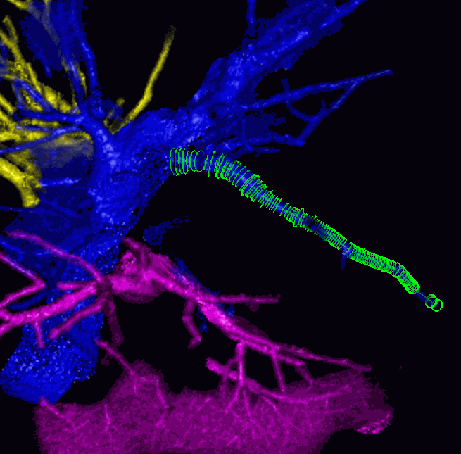
After segmentation has been completed, the tool remains active for work with the trees. The segmentation panel shows the structures created. To select a vessel, move the cursor to the vessel. To select a vessel and its subtrees, move the cursor while holding the Shift button. Figure 6.24 shows a vessel that has been selected.
To join a vessel to another tree, select the respective tree structure on the segmentation panel, choose the vessel with the cursor, so that it is highlighted, and click on it. The vessel and the structure will be the same colour.
The vessels that are not related to any trees are considered invalid. To disconnect a vessel from one tree without connecting it to any other trees, you just need to mark it as invalid. To do that, select the vessel with the cursor and double-click it or click holding down the Ctrl key (or the Command key for macOS) on the keyboard. Use the button with which the tool was activated. You can choose an incorrect vessel on the base volume holding down the Alt key (or the Option key for macOS) on the keyboard and join it to any tree.
After the tool has been deactivated, you can no longer select vessels, join them or mark as invalid.
To proceed with the trees created, click the Vessel tree segmentation button. A warning will
appear on the screen: The vessels are already computed for that volume. Do you
want to recompute them using current structure mask? click No in the dialog
box.
To perform vessels segmentation without deleting the results of the previous segmentation, choose
the structure (base volume), for which you need to perform segmentation, click the Vessel tree
segmentation button and click Yes in the dialog box. The vessels that have been created
after you used the tool for the last time will be selected.
6.8.5 Watershed segmentation tool
____________________________________________________________________________________________
Functionality is available in the Pro edition
____________________________________________________________________________________________
The tool is used for segment volume using the watershed method and allows you to split the volume into several non-overlapping parts.
The tool has two modes (directions for basin filling):
-
low dencity for the separation of soft tissues surrounded by more dense tissues: organs containing air, as well as the brain. In this case, the filling of the basins progresses from a lower tissue density to a greater one. The minimum density of tissues (Min dencity) is the point from which the filling of the basins begins, and the Max dencity value limits the density of the tissues to be segmented from above.
-
high dencity for separation of dense tissues surrounded by less dense tissues: bones and contrasted organs. In this case, the filling of the basins begins with the maximum density (Max dencity) and progresses in the direction of its reduction. The minimum density of the tissues to be segmented is limited from below by the Min dencity value.
To speed up the segmentation process and avoid the creation of unnecessary segments, exclude unnecessary tissues from the segmented volume, using the cutting tools.
To perform the Watershed segmentation:
-
Select the volume to be segmented.
-
If necessary, cut off the tissues that do not need to be segmented.
-
Activate the Watershed segmentation
 tool by clicking the left/right/middle
mouse button. To continue work with this tool, use the button with which the tool was
activated. To learn more about tool control, see Section 1.14.
tool by clicking the left/right/middle
mouse button. To continue work with this tool, use the button with which the tool was
activated. To learn more about tool control, see Section 1.14.
-
In the dialog that opens, set the following parameters:
-
Min dencity;
-
Max dencity;
-
Min depth: the minimum depth of basins which can be combined;
-
Max basins: the maximum number of created structures (no more than 31);
-
Select the mode (Low dencity, High dencity);
-
Select the source structure for segmentation from the Source drop-down list.
-
To set this structure as default, check the Remember selected structure box.
-
To hide the source structure, check the Hide source structure box.
-
To hide the structures which will not be changed after segmentation, check the Hide other structures box.
-
-
Click OK to perform segmentation or Cancel to cancel action. The process takes some time.
After the segmentation is complete, you can manually distribute the tissue into the basins, using the markers of the segmented structures. If the tissues do not fall into the required structure, it is necessary to install the markers corresponding to the structure on this tissue.
| | Warning! The structure changes made using markers cannot be undone! |
To perform the watershed segmentation using markers:
-
Select a structure on the list.
-
Activate the Segment marker
 tool by clicking the left/right/middle mouse button.
To continue work with this tool, use the button with which the tool was activated. To
learn more about tool control, see Section 1.14.
tool by clicking the left/right/middle mouse button.
To continue work with this tool, use the button with which the tool was activated. To
learn more about tool control, see Section 1.14.
-
Add one or more markers in the required places by clicking the mouse.
-
If necessary repeat steps 1-3 for the other structures.
-
Click the Watershed segmentation
button.
-
Make sure the Use structure markers box is checked.
-
Select the source structure for segmentation from the Source drop-down list.
-
To set this structure as default, check the Remember selected structure box.
-
To hide the source structure check, the Hide source structure box.
-
To hide the structures which will not be changed after segmentation, check the Hide other structures box.
-
Click OK to perform segmentation or Cancel to cancel action. The process takes some time.
If the markers of different structures are put in one basin then the segmentation fails.
The source structure is not modified. The structures without markers are not modified.
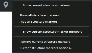
To show/hide markers for the selected structure, click on the right side of the Segment marker
button and check/uncheck the Show current structure markers box in the button menu
(Fig. 6.25). The selected item is marked with a flag.
To show/hide marker numbers for the selected structure check/uncheck the Show current structure marker numbers box. The option is disabled by default. This function simplifies work with structures having many markers. E.g., if a watershed segmentation attempt results in an error, this function helps you find out the number of the marker that caused this error. The selected item is marked with a flag.
To show/hide markers for all segmented structures, click on the right side of the Segment
marker button and select the Show all structure markers or Hide all structure markers
respectively.
To remove markers from the current segmented structure select the Remove current structure markers.
To change marker parameters of the selected structure, select the command Current structure markers options....
The other features of the segment markers are similar to those described in Section 5.12.
If segmentation is performed for a fused series, then only markers for the selected layer are displayed. Markers are editable regardless of which structure is selected.
For information on export and import of segmented structure markers, see Sections 6.7.8 and 6.7.9.
6.8.6 Multi-segment growing tool
____________________________________________________________________________________________
Functionality is available in the Pro edition
____________________________________________________________________________________________
This tool is used when it is necessary to increase masks of several structures so that they do not intersect. It is similar to Grow (dilation) (see Section 3.8.7), but can be applied simultaneously to an arbitrary number of structures and to the base volume. To use the tool:
-
Build the required number of structures whose masks you want to increase without intersection.
-
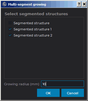
Activate the Multi-segment growing
 tool (see Section 3.8.7). The dialog shown
in Fig. 6.26 will be displayed.
tool (see Section 3.8.7). The dialog shown
in Fig. 6.26 will be displayed.
-
The currently selected structure (base volume) is marked with a flag in the dialog. Check all the structures (base volume) whose masks you need to simultaneously increase with flags. If only one structure (volume) is checked, then the tool works similarly to the Grow (dilation) tool.
-
Set the maximum growing radius in the Growing radius (mm) field.
-
Click OK to apply the tool or Cancel to cancel action. The process takes some time. If the building is incomplete, repeat steps 2-4.
-
To undo or redo the action, use the Undo
and Redo buttons for each
structure you have built up.
6.8.7 Segmented structures regions growing Tool
____________________________________________________________________________________________
Functionality is available in the Pro edition
____________________________________________________________________________________________
This tool is used when several masks of segmented structures are to be grown in one iteration (including within editing mask) so that they do not meet. To use this tool, you need at least one structure that is not empty.
Proceed as follows:
-
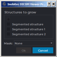
Click the Segmented structures regions growing
 button. The dialog box shown
in Fig. 6.27 will pop up.
button. The dialog box shown
in Fig. 6.27 will pop up.
-
In this dialog box, choose the structures whose masks to be grown.
-
If required, choose a structure or the main volume as the editing mask. You cannot choose the same structure for growing and as the editing mask.
-
Click OK to grow the structure or Cancel to cancel the operation. The process may take some time.
To undo this action, click the Undo button, to redo the action, click the Redo
button.
In the tab for viewing the volume reconstruction, the mask is grown within the color table assigned to this structure; in the tab for viewing the multiplanar reconstruction — within the green editing mask.
The growth speed has exponential relationship with the distance to the boundaries of the editing mask within which the structure is grown. It allows for effective division of the areas linked by narrow connectors.