5.12. Markers
5.12.1 General
A marker is a point, line or polygonal line in space, associated with a model. The DICOM Viewer allows you to display the length of the marker line and the polygonal marker line and the angles of the polygonal marker line.
The following tools are used to add markers: Marker, Line marker and Polygonal Line marker. To select one of these tools, click on the arrow on the tool selection button. The button will look different depending on the selected tool:
 | Marker (selected by default) |
 | Line marker |
 | Polygonal Line marker |
Activate/deactivate the currently selected tool by clicking the left/right/middle mouse button. To continue work with this tool, use the button with which the tool was activated. To learn more about tool control, see Section 1.14.
The added markers are located in the displayed slice.
For details on exporting and importing markers, see Sections 6.7.8 and 6.7.9.
5.12.2 Add Markers
To add a marker as a point:
-
Activate the Marker tool by clicking the
button on the toolbar.
-
Mark a place on an image by clicking the left mouse button. The marker will appear in all three windows.
After adding all the markers, deactivate the Marker tool.
This tool is also available from the image context menu and from the MPR main menu item. Activation is only possible with the left mouse button.
5.12.3 Add Line Markers
To add a Line marker:
-
Activate the Line marker tool by clicking on the
button on the toolbar. To
continue work with this tool, use the button with which the tool was activated. To learn
more about tool control, see Section 1.14.
-
A marker line can be built in two ways:
-
Mark the first point by clicking the mouse button. If required, go to the next section by rotating the mouse wheel. Move the cursor over the screen to the second point of the marker line. To fix the current point, click the mouse button.
-
Click the mouse button at the first point of the marker line and move the cursor to the endpoint while holding the mouse button. To go to the next section, rotate the mouse wheel while holding the mouse button. To fix the endpoint, release the mouse button.
-
-
To cancel an incomplete addition, press Esc.
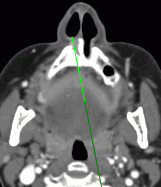
When building a marker line, the start and the end points are chosen on the selected sections. This allows for performance of measurements between the points placed on different sections. You can tell by the color of the marker line which part of it is in front of the current image. This part of the line will be brighter than the part placed behind the image (see Fig 5.23).
After adding all the line markers, deactivate the Line marker tool.
This tool is also available from the image context menu and from the MPR main menu item. Activation is only possible with the left mouse button.
Length measurements made with marker lines are saved in a file project.
5.12.4 Poilygonal Marker line
To add a Poilygonal Marker line:
-
Activate the Polygonal Line marker tool by clicking on the
button on the
toolbar.
-
Roll the mouse wheel to select the slice where the first point will be located.
-
Mark a point by clicking the mouse button.
-
If necessary, move to another slice by rolling the mouse wheel.
-
Move the mouse to select the location of the next point. Fix the point by clicking the mouse button.
-
Repeat steps 4 and 5 until the last but one point is fixed.
-
Fix the last point by double-clicking the mouse.
-
To cancel an incomplete addition, press Esc.
When building a polygonal marker line, the start and the end points, as well as the intermediate points, are chosen on the selected sections. This allows for performance of measurements between the points placed on different sections. You can tell by the color of the marker line which part of it is in front of the current image. This part of the line will be brighter than the part placed behind the image (see Fig 5.23).
After adding all the polygonal line markers, deactivate the Polygonal Line marker tool.
To continue the polygonal marker line, move the cursor to the end point of the line, right-click and select the Continue line item.
This tool is also available from the image context menu and from the MPR main menu item. Activation is only possible with the left mouse button.
The length and angle measurements made with polygonal marker lines are saved in the project file.
5.12.5 Actions with Markers
The following actions are available:
-
Drag a point or line and polygonal line marker points. Locate the cursor on the marker or point so that it would look like
 , and drag it, holding down the left mouse
button or the button to which this tool is assigned. The location of the marker will change
accordingly in all the windows. The marker will be moved parallel to the displayed slice.
, and drag it, holding down the left mouse
button or the button to which this tool is assigned. The location of the marker will change
accordingly in all the windows. The marker will be moved parallel to the displayed slice.
-
Remove. Locate the cursor on the marker so that it would look like
. Press the
Delete key on the keyboard or right-click the mouse and select the Remove marker
item.
-
Remove all the markers. If you need to delete all the markers, locate the cursor on any marker so that it would look like this:
, right-click the mouse and select the Remove
all markers item or select the corresponding item from the Marker tool menu.
5.12.6 Marker Properties
You can set the following properties:
-
Text;
-
Text size;
-
Diameter or Line width;
-
Color;
-
Show length (for Line Markers);
-
Show angle (for Polygonal Line Markers).
To set properties for previously added marker, locate the cursor over the marker, right-click and select the Set marker properties... item.
To set the default marker properties, click the arrow on the Marker button and select one of the Default marker options..., Default marker line options... or Default marker polygonal line options... items.
The parameters provided will be applied by default when new markers are added or new marker lines are built.
5.12.7 Position of Markers in Space
If the marker is in or near the current slice, it is displayed as a circle; otherwise, it is displayed as a ring with a dot in the center. The further the marker slice is from the current slice, the darker the marker is.
You can determine how the marker line is located relative to the plane of the current image, judging by the color of the marker line. The line (or its part) located in front of the plane is brighter than the line (or its part) behind the plane. In Fig. 5.23, the bottom part of the line is located behind the image.