2.17. Set Window Level and Width
The current window level and width values are displayed in the top right-hand corner of the
window. If the Adjust W/L  tool on the toolbar is active, these changes are made
holding the button which the tool was activated. To learn more about tool control, see
Section 1.14.
tool on the toolbar is active, these changes are made
holding the button which the tool was activated. To learn more about tool control, see
Section 1.14.
In the Volume Reconstruction tab or Multiplanar Reconstruction tab, you can also activate the tool from the right-click menu of the image. In the Flat Image Viewer tab, the tool is available in the Image section of the main menu. In the Multiplanar Reconstruction tab, the tool is available in the MPR section of the main menu. In the Volume Reconstruction tab, the tool is available in the Volume section of the main menu.
To change the parameters, move the mouse in the study window, holding the button which the tool was activated
-
to increase the window level — down;
-
to reduce the window level — up;
-
to reduce the window width — left;
-
to increase the window width — right.
For details on setting up the speed of changing the window width and level, see Section 2.17.5.
If you haven’t activated any tools with the right mouse button, you can change the window width and level by moving the mouse while holding the right button. In the Controllers tab of the Image viewer module (see Section 16.7.1), you can choose the mouse button which will be used by default to change the window parameters.
The procedure of changing the window width and level settings with touch gestures on a touchscreen monitor is described in Section 1.15.
The terms "window width" and "window level" in digital images commonly refer to "contrast" and "brightness" respectively on your computer.
For certain types of tissues, the DICOM Viewer has preset width and level values. To
change the width and level settings, click the arrow on the Custom W/L button  .
.
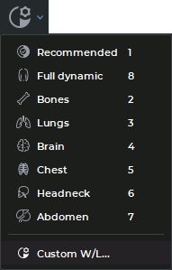
The following preset values are available in the drop-down menu (see Figure 2.23):
-
Recommended — the DICOM Viewer applies the values of the corresponding image tags. They are used by default.
-
Full dynamic — the mode where the window width and level depends on the image parameters available. This mode is used when the window width and level is not mentioned in the study.
-
Bones — for viewing bone tissues.
-
Lung — for viewing lung tissues.
-
Brain — for viewing brain tissues.
-
Chest — for viewing chest tissues.
-
Headneck — for viewing head and neck tissues.
-
Abdomen — for viewing abdominal tissues.
-
Custom W/L... — the window width and level parameters are provided by the user in the Window Level settings dialog box (see Figure 2.24) and are used for all the images in the series.
To select one of the modes without the preview option, click on the arrow on the button.
You cannot edit the values predefined for specific tissues. To return to the original settings, select the
Recommended mode.
To customize the window width and level settings, click the Custom W/L button
. In the Window Level settings dialog box (Figure 2.24) that pops up, provide the
window width and level parameters or choose the preset values you need from the Preset
dropdown list. On the Preset list, you will find standard preset values, as well as presets
saved by the user earlier (see Section 2.17.2). Standard preset values are marked with
icons.
In the Window Level settings dialogue box, you will see the hotkey and the window width and level settings assigned to the selected preset.
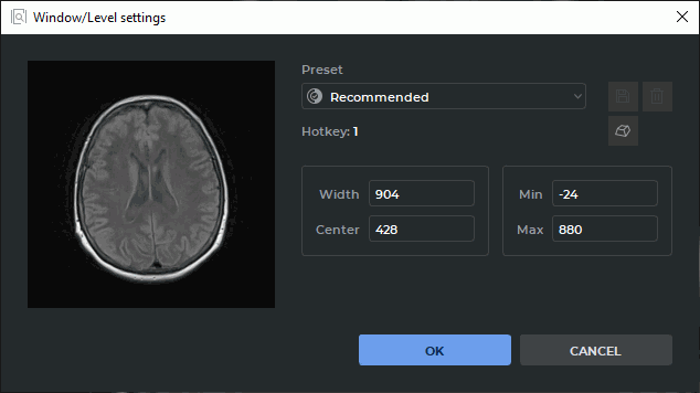
Click OK to apply the settings or CANCEL to cancel.
2.17.1 User Presets for Window Width and Level
There are two ways to create a user preset for window width and level:
-
Manually specify the values in the Width, Center, Min and Max fields of the Window Level settings dialog box. When a value is changed in one of the fields, the values in the other fields are changed automatically according to the following formulas:
Width = Max — Min;
Center = (Max + Min)/2.
If the window width and level settings provided are different from the existing presets, a <Custom W/L> value will be shown on the Preset dropdown list.
-
Change the window width and level settings with the Adjust W/L tool
(see
Section 2.17). Open the Window Level settings dialog box by clicking the button
on the toolbar.
If the window width and level settings provided are different from the existing presets, a <Custom W/L> value will be shown on the Preset dropdown list.
To save the provided window width and level settings as a new preset, click the Save preset  button in the Window Level settings window. In the New W/L preset dialog box that pops up
(see Fig. 2.25), provide the preset name and assign a hotkey to it. By default, the name assigned is in
the W<window width value>/L<window center value> format, and the Hotkey box remains
empty.
button in the Window Level settings window. In the New W/L preset dialog box that pops up
(see Fig. 2.25), provide the preset name and assign a hotkey to it. By default, the name assigned is in
the W<window width value>/L<window center value> format, and the Hotkey box remains
empty.
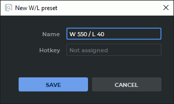
Provide a unique preset name. Assign a hotkey if required (see Section 2.17.2)
Click SAVE to save the preset or CANCEL to cancel.
After the new preset has been successfully saved, it will be shown in the Window Level settings dialog box.
2.17.2 Actions with presets
Actions with hotkeys. To assign or change a preset hotkey, proceed as follows:
-
Open theWindow Level settings dialog box by clicking the
key on the toolbar.
-
Choose the preset required from the Preset dropdown list.
-
Click the Set the hotkey
 button.
-
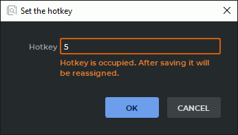
In the Set the hotkey dialog box that pops up (Fig. 2.26), provide a value in the Hotkey field. The permissible values are:
-
any single key on the alphanumeric keyboard or a function key, such as A or F5;
-
combinations of modifier keys Alt key (or the Option key for macOS), Ctrl key (or the Command key for macOS), Shift and alphanumeric or function keys pressed simultaneously, e.g. Ctrl+H (or the Command+H keys for macOS), Shift+F5, or Alt+Ctrl+Shift+Q (or the Option+Command+Shift+Q keys for macOS).
If the value specified in the Hotkey box is already assigned to another action or tool, a notification that the existing hotkey will be reassigned will appear in the dialog box. The user can also reassign hotkeys for standard window width and level settings.
-
-
Click "OK" to save the hotkey or CANCEL to cancel.
 | When a hotkey is reassigned, the user may have to relaunch the program for the changes to take effect. If the reassigned hotkey was assigned to another W/L preset, no relaunch is required. |
Deleting a user hotkey. To delete a user hotkey, proceed as follows:
-
Open the Window Level settings dialog box by clicking the
key on the toolbar.
-
Choose the preset to be deleted from the Preset dropdown list.
-
Click the Remove the preset
 button.
-
In the dialog box that pops up, click REMOVE to delete the preset or CANCEL to cancel.
| | Only the presets that were created earlier by the user can be deleted. Standard presets cannot be deleted. |
After the selected preset has been deleted, the previous preset on the list will be used as the current preset. The hotkey assigned to the deleted preset will be vacant.
User presets import and export. Window width and level presets will be exported and imported with other program settings (see Section 16.9).
2.17.3 Additional Width and Level Settings
To enable additional image viewer settings, proceed as follows:
-
Choose Settings... in the Options menu.
-
Choose Image viewer in the Modules list and click the Settings button.
-
From the Image viewer settings window, go to the W/L settings tab (Figure 2.27).
-
For the Flat Image Viewer mode, select the following options:
-
To calculate the Recommended and Full dynamic values and apply them to all the slices in the study, check the box Use the same W/L value for all images in Series. If you do not select this option, the Recommended and Full dynamic values will be calculated for each image separately.
-
If the window width and level values provided in the series tags are incorrect, check the box Recalculate recommended W/L. The recommended values are calculated on the basis of the image properties. The values provided in the series tags are ignored.
-
To set the default window width and level values for the DSA mode, check the Default DSA W/L. Provide the required numerical values in the Width and Center boxes.
-
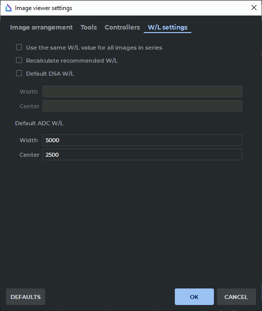
Click OK to apply the settings or CANCEL to cancel.
The options Use the same W/L value for all images in Series and Recalculate recommended W/L impact the window width and level values in the Recommended and Full dynamic modes.
To restore the default settings, click the DEFAULTS button.
2.17.4 Setting the Window Width and Level for Merged Series
To use the values provided in the Window Level settings dialog box (Figure 2.24) when viewing merged series, proceed as follows:
-
In the list of layers for the merged series, choose any except the first (base) layer. For details on series fusion, see Chapter 4. In the Window Level settings dialog box (Figure 2.24), provide the window width and level parameters or choose the preset values you need for this layer.
-
Open the merged series in the Volume Reconstruction or Multiplanar Reconstruction tab by pressing the respective button on the toolbar.
The width and level parameters for the first (base) layer are taken from the series tags. For the other layers, the width and level parameters are chosen by the user in the tab for merging layers.
2.17.5 Setting up the Speed of Changing the Window Width and Level (W/L)
The user can set the speed of changing the window width and level for the Adjust W/L tool.
To do that, click the arrow on the Adjust W/L button and select Parameters... In the
Adjusting W/L parameters dialog box (see Fig. 2.28), set the speed of changing the window
width and level.
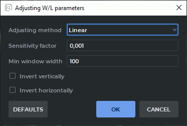
On the Adjusting method drop-down list, select one of the following options:
-
Linear. The window width and level values are changed in line with the movements of the cursor along the series window, while the mouse button with which the tool was activated is held down. This method is used by default;
-
Nonlinear (by mouse acceleration). The window width and level values are changed in line with the speed of the movements of the cursor in the series window. If the cursor moves fast, the values change faster, if the cursor moves slowly, the values change slower;
-
Nonlinear (by distance). The window width and level values are changed in line with the distance passed by the cursor in the series window. The changes depend on the distance between the initial position of the cursor (at the time the mouse button was pressed) and its current position.
For each method, additional parameters are configured:
-
the Sensitivity factor determines the rate of change of the level and window width values. Only positive real numbers can be entered in the field. The default value is 0.001;
-
for the linear editing method, in the Min window width field, specify the minimum window width at which the rate of change of W/L depends on the width. If the window width becomes smaller than the minimum, the rate of change of W/L stops decreasing. Entry of positive real numbers is allowed. The default value is set to 100;
-
for the nonlinear method (by mouse acceleration), in the Power field, specify the degree of increment of the W/L value based on changes in cursor speed. Entry of values greater than 1 is allowed. The default value is set to 2;
-
for the nonlinear method (by distance), in the Power field, specify the degree of increment of the W/L value based on the change in distance between the current and initial cursor positions. Entry of values greater than 1 is allowed. The default value is set to 2.5.
Users with individual experience related to the use of certain devices (trackball, joystick etc.) can change the window width and level in the direction opposite to the movements of the cursor. To invert the change of the window level, enable the Invert vertically option. To invert the change of the window width, enable the Invert horizontally option.
Click OK to apply the settings or CANCEL to cancel. To restore the default tool settings, click DEFAULTS.
| | If the color table (CLUT) High intensity or Low intensity is set as the current one, then, regardless of the selected editing method, a nonlinear method dependent on the cursor movement speed is applied with the following parameters: sensitivity factor — 0.1, power — 1.5. |