12.5. Marking Objects with Contours
____________________________________________________________________________________________
Functionality is available in a separate module which is activated in the Pro edition for an extra fee
____________________________________________________________________________________________
You can use contours to mark objects in DICOM images. Contours are drawn separately for each image (slice, phase, or frame) with the ROI object (contour) tool in the Image viewer tab in the image annotation mode.
To mark an object with a contour, proceed as follows:
-
Open a series in the Image viewer tab. Enable the image annotation mode (see Section 12.2).
-
If there is no tree of groups and classes on the image annotation panel, it must be imported or created.
-
In the line for the respective class on the image annotation panel, activate the ROI object (contour)
 tool with the left, right, or middle mouse button. Use the same
button to work with the tool. For details on the use of tools, see Section 1.14.
tool with the left, right, or middle mouse button. Use the same
button to work with the tool. For details on the use of tools, see Section 1.14.
-
Build a contour in one of the following ways:
-
building contours manually. Build a contour around the chosen area while holding the mouse button with which the tool was activated. To finish the procedure, release the mouse button. To cancel the contour that has not been closed, press Esc on the keyboard while holding the button;
-
building contours with an isoline. Move the cursor around the selected area while holding the Shift button on the keyboard. Under the cursor, you will see an isoline characterized by even points density. You can only see an isoline on the surfaces where a contour can be built. To build a contour with an isoline, click the left mouse button or the mouse button with which the tool was activated.
-
The color of the contour is the same as the color selected for the class of objects.
 | Contours can only be built for the orthogonal projection that was received from the modality. |
Contours may intersect if the Enable intersections of objects box in the object class parameters is checked for at least one of them. This box is checked by default.
To disable intersection of contours, uncheck the Enable intersections of objects box in the object class parameters. If intersection of contours is disabled, corrections will be made after a contour is built or edited: the shared areas will be deleted.
When a contour is built or edited, intersection of the current contour with those that have already been built may be prohibited. To prohibit intersection for the current contour, press and hold the Ctrl key (or the Command key for macOS) on the keyboard when finishing the building or editing procedure. The shared areas will be deleted.
If one of the contours is inscribed in the other, they are not considered intersecting.
12.5.1 Actions with Object Contours
____________________________________________________________________________________________
Functionality is available in a separate module which is activated in the Pro edition for an extra fee
____________________________________________________________________________________________
The DICOM Viewer provides for the following actions with object contours:
-
editing. To edit a contour, place the cursor over it. When you hover over the contour line, it is highlighted. Place the cursor over the area that needs editing and click the mouse button. Draw a new contour while holding the button. To finish the editing procedure, release the mouse button;
-
deleting. Place the cursor over the contour line, press the Delete key on the keyboard or click the right mouse button and choose the Remove object option from the right-click menu;
-
deleting all the Contours. To delete all the contours of the objects for the current series, choose the Remove all objects option from the right-click menu. In the dialog box that pops up, click YES to delete or NO to cancel.
12.5.2 Changing the Class of Object Contour
____________________________________________________________________________________________
Functionality is available in a separate module which is activated in the Pro edition for an extra fee
____________________________________________________________________________________________
 | If the current tree of object classes and groups is changed, it may result in incompatibility with the trees that were created earlier (see Section 12.3.4). |
To change the class of the object contour, proceed as follows:
-
Place the cursor over the contour. When you hover over the contour line, it is highlighted.
-
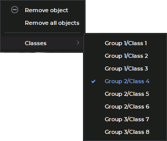
Click the right mouse button and select the Classes option from the right-click menu (Fig. 12.5). The group and the class of the selected object contour are ticked on the dropdown list.
-
Change the class of the object contour by selecting a suitable option from the list.
The characteristics of the selected class are applied to the contour.