5.7. Curvilinear Reconstruction
5.7.1 Build Surface
____________________________________________________________________________________________
Functionality is available in the Pro edition
____________________________________________________________________________________________
Curvilinear reconstruction is a section of tissues by a curvilinear surface whose configuration is set by the trajectory passing through the middle of this surface. This trajectory is called a curve.
To activate the Curvilinear reconstruction mode, click the Curve mode  . To get back to the
Multiplanar reconstruction mode, click the Curve mode button again. The curve built
in the Curvilinear reconstruction mode is not shown in the MPR reconstruction
mode.
. To get back to the
Multiplanar reconstruction mode, click the Curve mode button again. The curve built
in the Curvilinear reconstruction mode is not shown in the MPR reconstruction
mode.
To build a surface:
-
Select the plane in which it would be convenient to start building a curve.
-
Roll the mouse wheel to select the slice where the first point will be located.
-
Fix the first point on the image by clicking the left mouse button.
-
If necessary, move to another slice by rolling the mouse wheel.
-
Move the mouse to select the location of the next point. Fix the point by clicking the left mouse button. The point will appear in the current slice.
-
Repeat Steps 4 and 5 until the last but one point is fixed.
-
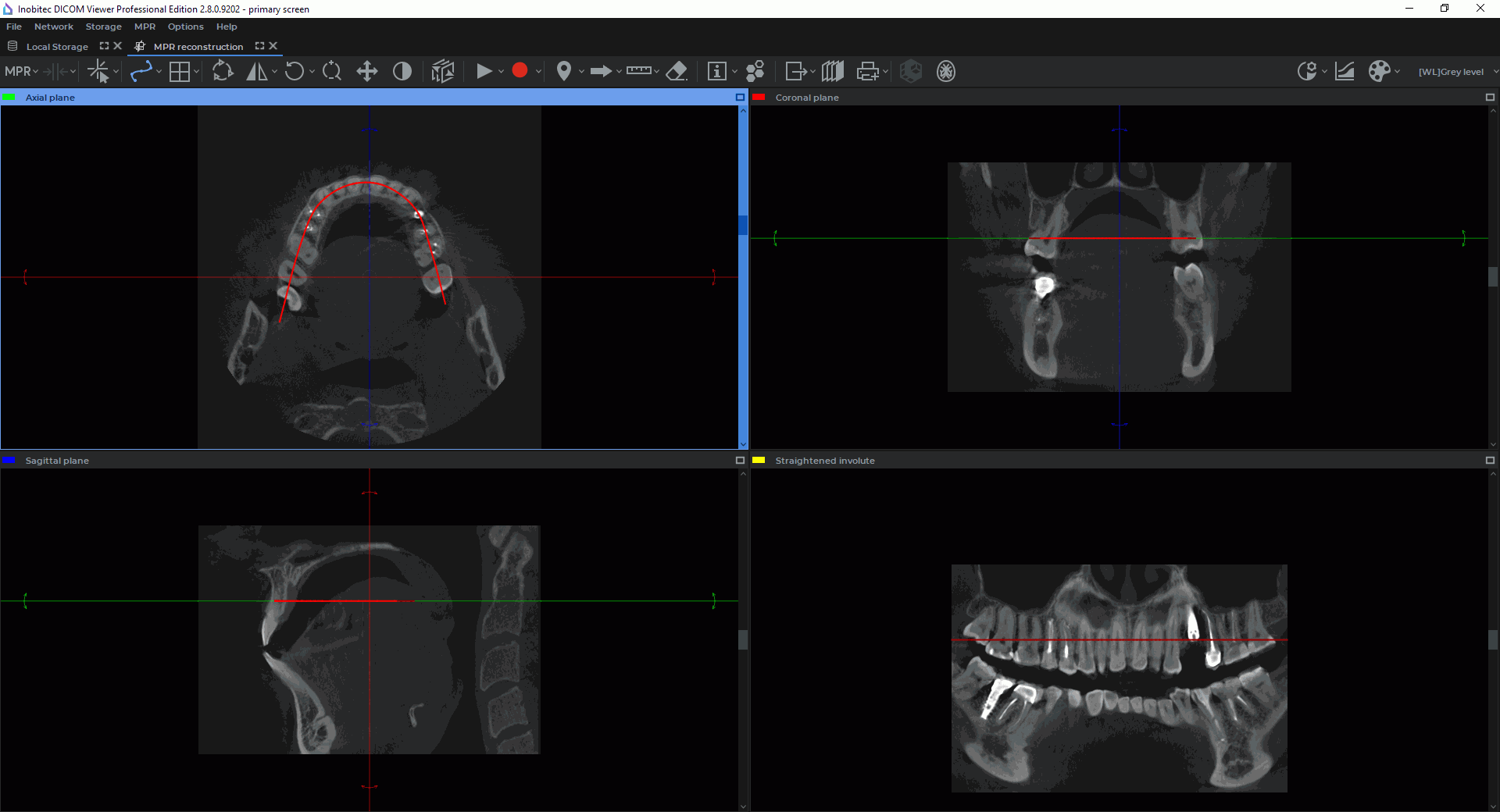
Fix the last point by left-clicking the mouse twice. While building the curve, the current section will be displayed in the bottom right-hand window. The other windows will display the projections of the curve on the corresponding planes (Fig. 5.8).
-
If necessary, correct the projections of the curve on the two other planes. For details on how to correct, see the section 5.7.4.
You can maximize any of the sectional plane windows from the MPR reconstuction tab and restore its size in several ways:
-
click on the
 Expand button in the right-hand upper corner of the series window;
-
double-click with the left mouse button on the title of the series window.
You can maximize and restore the size of the Involute window using the first or second method.
5.7.2 Choosing a Display Mode for an Involute of a Curve
____________________________________________________________________________________________
Functionality is available in the Pro edition
____________________________________________________________________________________________
Click the arrow on the Curve mode button and choose the display mode for the involute
of the curve from the button menu (Fig. 5.9). The current mode is ticked.

-
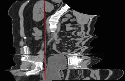
Straightened involute. The mode is set by default. In the straightened involute curve window (Fig. 5.10), the curve built by the user is transformed into a straight line. The distortions of space along the curve are marginal and increase with distance from the curve. We recommend this mode when the region of interest is placed near the curve. This option provides for the highest possible level of detail along the curve.
-
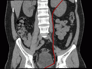
Involute curve in orthogonal planes (Fig. 5.11). Unlike the Straightened involute mode, this mode provides for a lower distortion degree at a distance from the curve, but the level of detail along the curve is also lower. Unlike the Involute curve from first to last point, this mode is less dependent on the position of points on the curve. It is used when you need an involute similar to an orthogonal projection. The orthogonal projection is chosen automatically to provide for the highest possible level of detail along the curve. Still, the level of detail along the curve is lower compared to other curve modes.
-
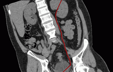
Involute curve from first to last point (Fig. 5.12). Compared to the Straightened involute mode, the distortion degree at a distance from the curve is lower, but the level of detail along the curve is also lower. The involute is highly dependent on the position of the first and the last point on the curve. The level of detail along the curve is greater than in the Involute curve in orthogonal planes mode.
The selected curve mode will be applied the next time the Curvelinear Reconstruction mode is activated.
In the Straightened involute mode, the Ruler, Polygonal Ruler, Angle, and Kobb angle tools cannot be used in the window with the involute.
5.7.3 Curve settings
____________________________________________________________________________________________
Functionality is available in the Pro edition
____________________________________________________________________________________________
The parameters of the curve can be set in the Curve options dialog box (Fig. 5.13). The appearance and the functions of the Curve options dialog box depend on the way you call for it. There are two ways to call for the Curve Options dialog box:
-
Click the arrow on the Curve mode
button on the toolbar and then select Default
curve options... from the button menu. You will see the dialog box shown in Fig. 5.13a.
-
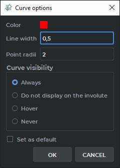
Right-click on the curve or a point on the curve and select Curve options... from the menu that pops up. You will see the dialog box shown in Fig. 5.13b.
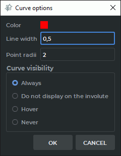
You can set up the following parameters:
-
color;
-
line width in pixels;
-
point radius in pixels.
Setting the curve visibility mode:
-
Always. When the curve is being built, it is shown in all the windows of the tab with plane projections, as well as in the involute window. After the curve has been built, it is always shown in all the windows of the tab with plane projections, as well as in the involute window. This mode is set by default.
-
Do not display on the involute. When the curve is being built, it is shown in all the windows of the tab with plane projections, except for the involute window. After the curve has been built, it is always shown in all the windows of the tab with plane projections, except for the involute window.
-
Hover. When the curve is being built, it is shown in all the windows of the tab with plane projections, as well as in the involute window. After the curve has been built, it is shown in all the windows of the tab with plane projections, as well as in the involute window if the cursor is placed on the curve.
-
Never. When the curve is being built, it is shown in all the windows of the tab with plane projections, as well as in the involute window. After the curve has been built, it is hidden. Choose another visibility mode to see the curve.
If you open theCurve options window from the Curve mode button menu (Fig. 5.13a), the settings will always be applied to the curve by default.
If you tick the Set as default box in the Curve options dialog window opened from the curve context menu (Fig. 5.13b), the settings will be applied by default when a curve is built.
To apply the settings, click OK. To cancel, click CANCEL.
5.7.4 Actions with a Curve
____________________________________________________________________________________________
Functionality is available in the Pro edition
____________________________________________________________________________________________
Actions with a curve can be performed only if the curvilinear reconstruction mode is active.
The following actions are available:
-
Drag a point. Locate the cursor on the point so that it enlarges, and drag the point holding down the left mouse button or the button to which this tool is assigned. Then release the mouse button.
-
Add a point. Locate the cursor on the curve where the point should be added. Right-click the mouse and select the Add point item.
-
Delete a point. Locate the cursor on the point. Right-click the mouse and select the Remove point item.
-
Continue a curve. Locate the cursor on one of the border points of the curve. Right-click the mouse and select the Resume curve item. Then, perform Steps 3 and 4 of the curve building algorithm.
-
Delete a curve. Locate the cursor on any position on the curve or on a point. Right-click the mouse and select the Remove curve item.
5.7.5 Position of a Curve, Its Nodes and Surface in Space
____________________________________________________________________________________________
Functionality is available in the Pro edition
____________________________________________________________________________________________
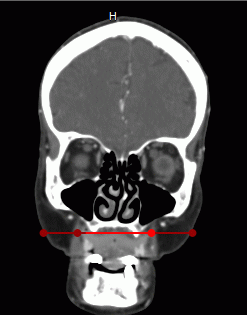
By the color of the curve, you can determine which part of the curve is located in front of the current image in space. This part of the curve is brighter than the part behind the image.
In Fig. 5.14, the central part and the third point are a brighter color. This means they are located in front of the current section.
To make it easier to find a node on the curve on all the projections, locate the cursor on this node. The node will be magnified on all the projections.
To rotate the surface relative to the curve, move the cursor to the bottom right-hand window (Surface by curve) and roll the mouse wheel.
To move the cutting planes to the selected point of the curve, move the mouse cursor to the selected point on the curve in the selected window. Left-click while holding down the Ctrl key (or the Command key for macOS) on the keyboard. The point of intersection of the cutting planes is moved to the specified point on the curve in all the windows.
5.7.6 Curved Reconstructions Cross Sections Mode
____________________________________________________________________________________________
Functionality is available in the Pro edition
____________________________________________________________________________________________
The curved reconstruction cross section mode is aimed for viewing the planes that are perpendicular to the curve and evenly spaced.
You can view curve slices if Curvelinear reconstruction mode is activated and a curve has been
built. To activate the Curvilinear reconstruction mode, click the Curve mode button
.
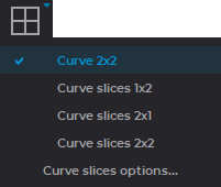
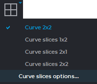
To select the window arrangement template, click the arrow on the button or the Switch layout
template button  and choose one of the options provided (see Figure 5.15):
-
Curve 2x2. In the MPR reconstruction tab, you see three windows with
multiplanar reconstruction cutting planes and a Involute window. This mode is selected
by default.
-
 Curve slices 1x2. The tab is divided into two windows. The Involute window is
placed at the top, and the Curve slices window is at the bottom.
Curve slices 1x2. The tab is divided into two windows. The Involute window is
placed at the top, and the Curve slices window is at the bottom.
-
 Curve slices 2x1. The tab is divided into two windows. The Involute window is
placed on the left-hand side, and the Curve slices window is on the right-hand side.
Curve slices 2x1. The tab is divided into two windows. The Involute window is
placed on the left-hand side, and the Curve slices window is on the right-hand side.
-
 Curve slices 2x2. The tab is divided into four windows. The Axial projection
and the Volume reconstruction windows are placed on the left-hand side, while the
Involute and the Curve slices windows are placed on the right-hand side.
Curve slices 2x2. The tab is divided into four windows. The Axial projection
and the Volume reconstruction windows are placed on the left-hand side, while the
Involute and the Curve slices windows are placed on the right-hand side.
The window arrangement template settings will be applied next time you choose the Curve mode.
You can maximize any of the sectional plane windows from the MPR reconstuction tab and restore its size in several ways:
-
click on the
Expand button in the right-hand upper corner of the series window;
-
double-click with the left mouse button on the title of the series window.
You can maximize and restore the size of the Involute, 3D view and Curve slices windows using the first or second method.
If you see the Volume reconstruction window or the segmentation panel in the tab, the volume editing tools are available.
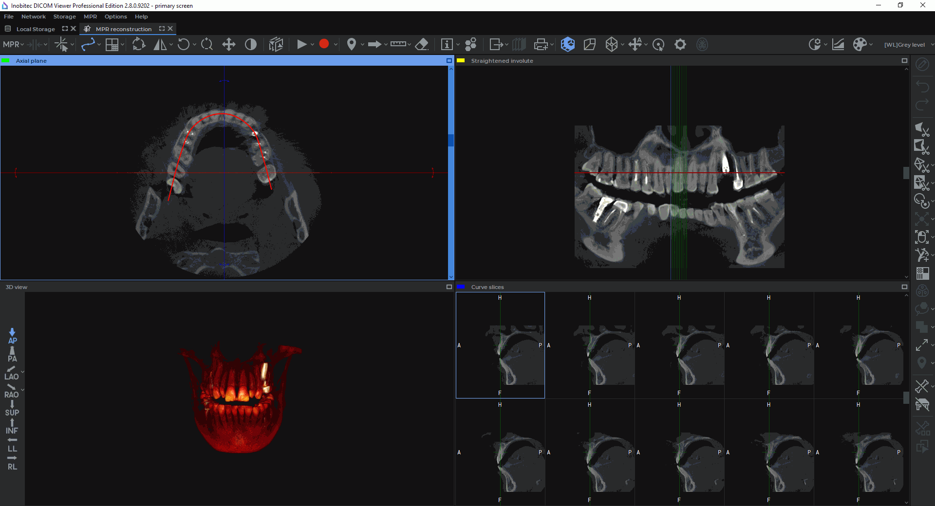
In the Involute window, a straightened curve and perpendicular cutting planes projections are shown. When you mouse over a cutting plane in the Involute window, the respective plane and projection will be highlighted. The point in which the cutting plane crosses the curve will be marked with a crosshair in the slices window.
To rotate the surface round the curve, mouse over the Involute window and scroll the mouse wheel or move the slider in the slices window.
To move the cutting planes along the curve, mouse over the slices window and scroll the mouse wheel or move the slider in the slices window.
To move the cutting planes automatically, activate the Play  tool (see Section 5.10).
To set the curve slices parameters, click the arrow on the button or the Switch layout template
button and choose the Curve slices options... (Figure 5.17).
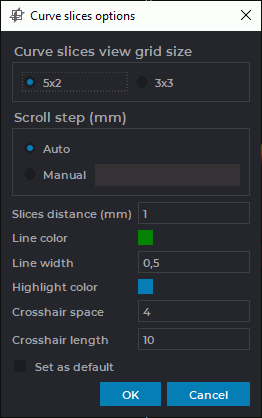
A dialog box will pop up (Fig. 5.18), in which you can set the following parameters:
-
the size of the slices window grid. Choose the suitable number of rows and columns (5x2 or 3x3);
-
the distance between slices (in millimeters);
-
the scrolling increment. Choose one of the two variants: Auto (the increment is equal to one voxel) or specify the increment in millimeters;
-
the color of the cutting plane lines;
-
the thickness on the cutting plane line and the crosshair in pixels;
-
the color of the selected cutting plane line and the frame of the slices window;
-
the crosshair space in pixels. Set the distance from the lines forming the crosshair to its virtual center;
-
the size of the crosshair in pixels.
If you have checked the Set as default box, these settings will be used by default when you switch to the Curve slices mode.
There are two ways to activate the Curve slices options dialog box from the right-click menu:
-
Mouse over one of the cutting planes in the Involute window. Right-click and choose Set curve slices options...
-
Mouse over the crosshair of one of the slices in the slices window. Right-click and choose Set curve slices options...
Rotate, Zoom, Pan and Adjust W/L tools are simultaneously activated for all the slices.
DICOM Viewer records videos, exports and prints images from the Involute window or the slices window, whichever is active.
In the slices window, only the image from the top left-hand cell will be printed. To print or export the slice you need, move the cutting planes along the curve, so that the slice you need appears in the top left-hand cell. You can move the cutting planes by scrolling your wheel or moving the slider in the slices window.
In the slices window, video is recorded for the top left-hand cell. To record a video for the slice you need, move the cutting planes along the curve, so that the slice you need appears in the top left-hand cell.
To record a video, activate the Start video record tool  (see Section 5.11).
To escape from the curve slices mode, click the Curve mode button.