6.1. The Segmented Structures Panel
____________________________________________________________________________________________
Functionality is available in the Pro edition
____________________________________________________________________________________________
To open the segmented structure panel in the MPR reconstruction and Volume
reconstruction tabs, click the Segmented structure panel  button on the toolbar.
The segmented structures panel for the MPR reconstruction tab is shown in Fig. 6.3. This panel is identical in the Volume reconstruction tab, except that the MPR MPR nested element is not displayed for the base volume.
The panel contains the Control buttons:
 | The Parameters button is used to call up the popup menu for surface creation parameters setup and export/import parameter setup (see Section 6.7). |
 | The Save segmentation project to file button is used to call up the dialog box for saving a segmentation project in a file (see Section 6.11). |
 | The Open segmentation project from file button is used to call up the dialog box for opening a segmentation project saved in a file (see Section 6.11). |
 | The Add a new structure button creates a new structure with an empty mask. |
 | The Create surface for current segment button creates a surface for a selected structure or for the base volume. |
 | The Import masks from DICOM RT mask set... button imports a mask of segmented structure from DICOM RT (see Section 6.7.5). |
 | The Import surface(s) button imports a segmented structure from ply, obj or stl file formats. |
 | The Duplicate structure/Duplicate mask/Duplicate surface button, depending on the element selected on the segmentation panel, makes a copy of the whole structure, the mask of structure, or the surface in a separate structure (see Section 6.3.1). If the Structure or Base volume option has been selected, the structure Mask and the Surface (when built) are copied to the new structure. If the MPR, Base volume, or structure Mask option has been selected, only the structure mask is copied to the new structure. If the Surface option has been selected, only the surface is copied to the new structure. |
 | The Restore base volume by mask makes the main volume the same as the selected segmented structure. For the MPR reconstruction tab, the 3D view window must be activated. |
 | The Remove structure/Remove surface button deletes either the whole structure or the surface depending on the option selected on the hierarchical list. When a structure is deleted, a confirmation dialog box pops up. |
 | The Export button opens export menu for surfaces and masks. |
 | The
Hide
all
masks/Show
all
masks
button
is
used
to
hide/display
the
masks
for
the
base
volume
and
the
structures
on
the
segmentation
panel.
When
all
the
masks
are
hidden,
the
icon
is
replaced
by
a
crossed
out
version
 .
. |
 | The
Hide
all
surfaces/Show
all
surfaces
button
is
used
to
hide/display
all
the
surfaces
for
the
base
volume
and
the
structures
on
the
segmentation
panel.
When
all
the
surfaces
are
hidden,
the
icon
is
replaced
by
a
crossed
out
version
 .
. |
 | The Optimal view button is used to display all the elements of the list up to the third nesting level and hide all the elements from the third nesting level. |
 | The Collapse all button collapses all the elements of the list on the segmentation panel except layer items. |
 | The Expand all button shows all the elements of the list on the segmentation panel. |
 | The Surface positioning button changes spatial orientation and scale of the imported surface. (only for the 3D reconstruction window). The tool may be activated with the left, right, or middle mouse button. To continue work with the tool, use the button with which the tool was activated. For details on tool control, see Section 1.14. |
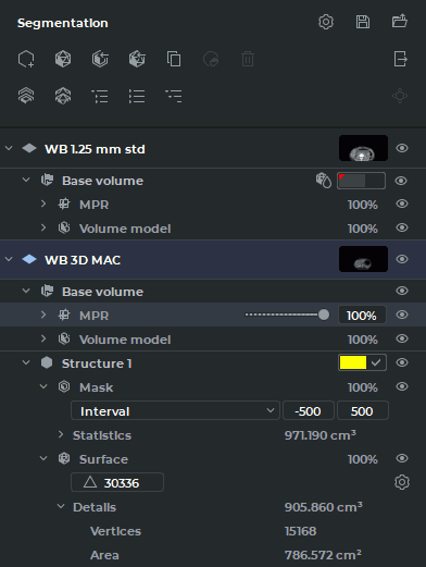
The hierarchical list of items on the segmented structures panel consists of the list of layers and the list of segmented structures for each layer.
By default, the optimal view of the list is presented (the items up to the third nesting level are
shown). To see all the items, click the Expand all button on the segmented structures panel.
To see some particular items, press the arrow on the left-hand side of the name of the
item.
In the line referring to the layer, you can see a description of the layer, a thumbnail for the layer
series, and a button for customizing visibility  of the layer and all the child items for this layer.
The layer includes the base volume and a list of segmented structures. The layer consists
of:
of the layer and all the child items for this layer.
The layer includes the base volume and a list of segmented structures. The layer consists
of:
-
Base volume. In this line, the visibility
button for the base volume and all the child
items is shown. If a surface has been created for the base volume, then the  symbol is
shown in the line. The color of the surface is the same as the color of the initial model.
Alternatively, the user may select the color (see Section 6.4). The Base volume item comprises
the following elements:
symbol is
shown in the line. The color of the surface is the same as the color of the initial model.
Alternatively, the user may select the color (see Section 6.4). The Base volume item comprises
the following elements:
-
MPR (shown only in the MPR reconstruction tab). It comprises a visibility
button for the item and child items, as well as a field showing the current
opacity value for MPR windows. When you mouse over the respective line,
a slider is shown. To change the opacity value, move the slider or enter the
required numeric value in a percentage. The MPR comprises the following
items:
-
a CLUT settings control element for the MPR reconstruction tab;
-
Statistics. This item provides for the results of base volume measurements. Besides the visible voxel volume, the minimum, maximum, and average intensity values are shown, as well as the standard intensity value deviation. When tissues are cut off with the Clipping Box tool, only the statistics for the base volume is affected. It has no impact on the statistics for segmented structures;
-
-
Volume model. It comprises a visibility
button for the base volume, as well as
a field showing the current opacity value for the 3D view window and the
Volume reconstruction tab. When you mouse over the respective line, a slider
is shown. To change the opacity value, move the slider or enter the required
numeric value in a percentage; The Volume model comprises the following
items:
-
a CLUT settings control element for the 3D view window and the Volume reconstruction tab;
-
Statistics. This item provides for the results of base volume measurements. Besides the visible voxel volume, the minimum, maximum, and average intensity values are shown, as well as the standard intensity value deviation. When tissues are cut off with the Clipping Box tool, only the statistics for the base volume is affected. It has no impact on the statistics for segmented structures;
-
-
Surface (if created). It comprises a visibility
button for the surface, as well as a field
showing the current opacity value. When you mouse over the respective line,
a slider is shown. To change the opacity value, move the slider or enter the
required numeric value in a percentage. The Surface comprises the following
items:
-
a field for changing the number of triangles forming the surface;
-
the Change surface creation parameters
button used to call up the
dialog box for customizing the surface parameters;
-
Details. This item provides the information about the volume of voxels around which the surface was built, the number of vertices and the surface area.
-
-
In the Structure line for the segmented structure, you see the name of the structure, color control
elements, and a visibility button for the structure and its child items. The Structure
comprises the following items:
-
Mask. This element is used for control of the segmented structure voxel model, and its structure is similar to the Volume model element. It comprises a visibility
button
for the structure mask. When you mouse over the respective line, you see the current
structure mask opacity value. To change the opacity value, move the slider or enter the
required numeric value in a percentage.
-
Surface. This element is used for customizing the surface settings, and its structure is similar to the Surface element for the layer.