3.8. Cutting Tools
There are several cutting tools on the right toolbar.
3.8.1 Polygon Cut
The Polygon Cut  tool allows you to build a polygon or an area with smooth borders that the
cut area is projected on.
tool allows you to build a polygon or an area with smooth borders that the
cut area is projected on.
To build a polygon:
-
Activate the Polygon Cut tool by clicking the left/right/middle mouse button. To continue work with this tool, use the button with which the tool was activated. To learn more about tool control, see Section 1.14.
-
Click the mouse button to set the apices of the polygon marking the figure to be cut, except the last point.
-
Fix the last point by double-clicking the mouse.
-
To cancel an incomplete building, press Esc.
To build an area with smooth borders (Lasso mode):
-
Activate the Polygon Cut tool by clicking the left/right/middle mouse button. To continue work with this tool, use the button with which the tool was activated. To learn more about tool control, see Section 1.14.
-
Press and hold the Shift key on the keyboard.
-
Circle the area to be cut, holding down the mouse button.
-
To complete the building, release the mouse button or click another mouse button.
-
To cancel an incomplete building, press Esc.
The part of the model to be projected on the area will be cut.
3.8.2 Inverse Polygon Cut
The tool is similar to the previous one, except that the part of the model not to be projected on the
area will be cut. To activate/deactivate the tool, use the  button on the toolbar.
3.8.3 Cut object
The tool allows you to delete an area of a 3D model not associated with its other parts.
Activate/deactivate the  tool by clicking the left/right/middle mouse button. To continue
work with this tool, use the button with which the tool was activated. To learn more about tool
control, see Section 1.14.
tool by clicking the left/right/middle mouse button. To continue
work with this tool, use the button with which the tool was activated. To learn more about tool
control, see Section 1.14.
3.8.4 Cut all except object
The tool is similar to the previous one, except that all areas excluding the selected area are deleted.
To activate/deactivate the tool, use the  button on the toolbar.
3.8.5 Cutting Tools Parameters
For the Cut object and Cut all except object tools, the following parameters can be set:
-
Grow from surface (mm). The tissue surrounding the deleted area will be deleted too. This parameter specifies the distance from the surface on which the tissue will be deleted. If this parameter is set to zero, the model surface may look rough, so use a value of zero only if necessary.
-
Min object thickness (mm). If the value is greater than zero, the tissue with a thickness less than the set value will be ignored during deletion.
The parameters for each tool are set separately.
To set these parameters, click on the arrow on the appropriate tool button and select the Parameters... item and in the dialog box that appears, specify the required values.
3.8.6 Brush Tools for Editing Volume
____________________________________________________________________________________________
Functionality is available in the Pro edition
____________________________________________________________________________________________
The Brush cut  , Brush restore
  and Restore by mask
  tools
allow to remove tissue within a sphere or cylinder and restore the tissue deleted by cutting
tools.
tools
allow to remove tissue within a sphere or cylinder and restore the tissue deleted by cutting
tools.
The Brush opening  and Brush closing
  tools are aimed for smoothing tissues and
deleting hollows in the tissues of the model.
tools are aimed for smoothing tissues and
deleting hollows in the tissues of the model.
The brush tools for editing volume are assigned to the same button. To select a tool, click on the arrow on the tool selection button. The button looks different, depending on the tool selected:
| | Brush cut (is selected by default) |
| | Brush restore |
| | Brush opening |
| | Brush closing |
| | Restore by mask |
To select one of modes (Sphere, Cylinder), click the arrow on the tool buttons. The same mode is used for all the brush tools for editing volume.
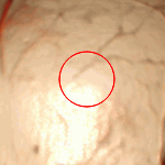
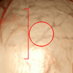
The cursor will look different depending on the mode that is selected. The cursor for the Sphere mode is shown in Fig. 3.6, and the cursor for the Cylinder mode is shown in Fig. 3.7.
To activate/deactivate the tool, click on the tool button. If any tool is activated, the button is highlighted.
To cut tissue:
-
Activate the Brush cut
tool by clicking the left/right/middle mouse button. To
continue work with this tool, use the button with which the tool was activated. To learn
more about tool control, see Section 1.14.
-
Select the tool mode from the menu.
-
Set the tool diameter, moving the mouse while holding the Alt key (or the Option key for macOS). The Brush cut, Brush restore, Brush opening and Brush closing tools are set to the same diameter value.
-
For the Cylinder mode, set the height if it is necessary. To do it, click the arrow on the tool button and select the Cylinder options... item. In the dialog box that appears, set the cut height.
-
Click the mouse button in the place where you want to cut tissue. Part of the tissue will be cut. The green dot indicates where the great circle of the sphere (the base area of the cylinder) touches the surface of the model. The great circle passes through the center of the sphere and is parallel to the plane of the screen.
-
Repeat steps 3 and 5 if necessary.
The Brush restore tool allows you to perform the reverse process of brush
cutting.
The Brush opening tool is used for removing random elements (noise) and smoothing
tissues on the model. It implies successive erosion and dilatation within the region limited by the
tool.
The Brush closing tool is used for deleting small hollows in the model. It implies
successive dilatation and erosion within the region limited by the tool.
To set the radius for the brush opening/closing morphological operation, click the arrow on the tool button and select the Morphological operation radius... option. In the dialog box that pops up, provide the radius in millimeters or voxels. The same morphological operation radius is set for the Brush opening and Brush closing tools.
The Restore by mask tool allows you to restore tissue by mask (this tool is used for
segmentation). If mask is not set, this mode is analogous to the Brush restore mode. For details
how to set mask, see Section 6.2.4.
3.8.7 Tools for intelligent volume editing
____________________________________________________________________________________________
Functionality is available in the Pro edition
____________________________________________________________________________________________
The Grow (dilation), Shrink (erosion), Fill and Cut invisible volume tools allow to edit tissue within special algorithms. The Multi-segment growing (Voronoi diagram) tool allows you to edit segmented structures. To select one of these tools, click the arrow on the tool buttons. The button will look different depending on the tool that was used last:
 | Grow (dilation) (set by default) |
 | Shrink (erosion) |
 | Remove noise (opening) |
 | Remove holes (closing) |
 | Multi-segment growing (Voronoi diagram) |
 | Fill |
 | Cut invisible volume |
The Grow (dilation) tool allows you to increase the volume by a certain value from the surface in one iteration. This value is specified in the Settings menu of this tool (parameter Growing radius). The increase is possible only within the original volume, for example, after the use of cutting tools. When you use this tool to edit a segmented structure, an increase is possible only within the mask. The tool is used to fine-tune the structure if, initially, the required volume was not obtained.
The Shrink (erosion) tool performs the opposite action. The reduction value is specified by the parameter Growing/Shrinking radius.
The Remove noise (opening) tool allows to remove noise from the volume. This tool is equivalent to the consistently applied tools Shrink (erosion) and Grow (dilation).
The Remove holes (closing) tool allows to remove little holes from the volume. This tool is equivalent to the consistently applied tools Grow (dilation) and Shrink (erosion).
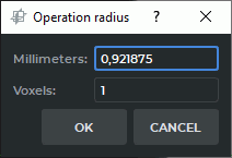
Each time the Grow (dilation), Shrink (erosion), Remove noise (opening), and Remove holes (closing) tools are used, a dialog box (Fig. 3.8), in which the operation radius should be set in millimeters or voxels is displayed.
The Multi-Segment Growing (Voronoi diagram) tool allows you to simultaneously build several structures and base volume. It is used to edit segmented structures (see Section 6.8.6). If the tool is applied only to the base volume, then it works like the Grow (dilation) tool.
The Fill tool allows you to fill the voids in the volume. If you are working with segmented structures, the tool is used to improve structures, built on a "grainy" mask. Such masks are typical, for example, for kidneys.
The Cut invisible volume tool sets the mask according to the visible volume. On the 3D model, the voxels that are not shown for the selected color table or the set window width and level (W/L) values are deleted. If the color table or the window width and level (W/L) values are changed later, the deleted voxels are not restored. The Cut invisible volume tool is available in the Volume reconstruction tab and in the 3D view window of the MPR reconstruction tab.
3.8.8 Remove Table
The tool allows you to delete areas resembling the medical equipment table. To delete, click the  button on the toolbar.
 | Some objects that have been misrecognized as the modality table may be deleted by mistake. |
To undo or redo the last action associated with cutting, use the Undo  and Redo
  buttons.