5.8. Displaying Section Planes on 3D Models
The MPR planes on 3D view  tool is used for setting up and displaying section planes on 3D
models in the 3D view window.
tool is used for setting up and displaying section planes on 3D
models in the 3D view window.
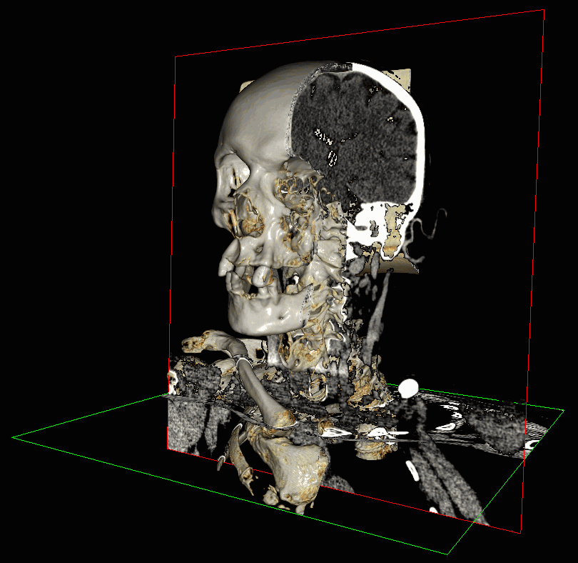
The tool is available on the toolbar in MPR reconstuction, Vessel analysis and Coronary artery analysis tabs only when a 3D reconstruction is displayed in the 3D view window. In the Fig. 5.19, , you can see an example of section planes displayed on a 3D model in the 3D view window of the MPR reconstuction tab.
To enable the mode for displaying section planes, click the MPR planes on 3D view
button on the toolbar.
 | The
tool
is
only
available
when
a
3D
reconstruction
is
displayed
in
the
3D
view
window.
To
enable
the
3D
reconstruction
display
mode,
click
the
3D
 button
on
the
toolbar.
button
on
the
toolbar. |
To enable the planes display, click the arrow on the MPR planes on 3D view button and
select the display mode on the button menu (see Fig. 5.20):

Planes of open windows. In the 3D view window, the section planes that are shown in the open windows of the tab are displayed. This mode is enabled by default.
To enable the display of certain cutting plains, disable the Planes of open windows mode. You can enable the display of the following planes:
-
Axial plane;
-
Coronal plane;
-
Sagittal plane;
-
Curved surface(PRO). A curvilinear surface may be displayed in the 3D view window after a curve is built (see Section 5.7.1). On the curvilinear surface plane, the centerline is shown in dark red;
-
Curved slice plane(PRO). The curve slices are displayed when the curve slices window is opened for the first time (see Section 5.7.6). In the 3D view window, the plane of the first slice is displayed.
All the planes are displayed by default.
Borders of the planes. The mode is used to enable/disable the display of borders of the cutting planes on a 3D model. The display of borders of the planes is enabled by default.
Transparency settings. In the dialog box that pops up (Fig. 5.21), move the slider to set up the planes transparency. The extreme right position equals maximum opacity. The maximum opacity level is set by default.
| | Planes transparency is not supported:
|
To make the background visible, uncheck the Transparent background box. The box is checked by default. To close the transparency settings dialog box, click the CLOSE button.
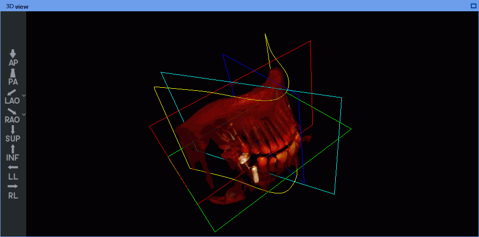
The colors of the plane borders are the same as the colors of the windows of the respective cutting planes. On the curvilinear surface plane, the centerline is shown in dark red. The borders of the curve slice plane are shown in blue.