16.7. Modules
In this section you can specify the settings for particular modules (Fig. 16.4).
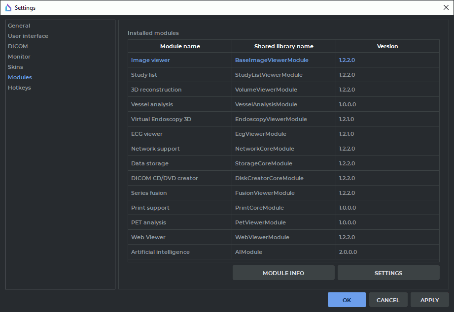
To browse the detailed information about each module, select the module and click the Module info button. For some modules, special parameters are set. To do this, select the module from the Installed modules list and click the SETTINGS button.
16.7.1 Set Up Image Viewer Module
Select the Image Viewer module from the Installed modules and click the SETTINGS button. The Image viewer settings window contains four tabs with the following parameters:
-
General tab. The following parameters are set up:
-
default tool (the one that activates when opening an image). Options:
-
no tool;
-
Adjust W/L;
-
Ruler;
-
Angle;
-
ROI rectangle tool;
-
ROI ellipse tool;
-
ROI polygon tool;
-
Sync by point;
-
-
default mode. Options:
-
no mode selected;
-
DSA mode;
-
-
request for confirmation before deleting all annotations and measurements;
-
enable/disable the warnings of non-bilinear interpolation;
-
show TSE values in annotations;
-
enable/disable default synchronization of series image scrolling;
-
enable/disable slices scaling and position synchronization for various projections;
-
enable/disable display of the series list for the current study on the context menu. The function is enabled by default.
-
-
Image arrangement tab. The following parameters are set up:
-
Confirm series closure on the arrangement changing option. The option is enabled by default. Switches off/on the display of the dialog box for series deletion confirmation when the user selects a grid with fewer view windows than there are open series in the study. The option is exported to the file saving the current DICOM Viewer settings (see Section 16.9.1);
-
default series arrangement;
-
splitter priority;
-
default image arrangement;
-
the number of images scrolled per click;
-
Automatic fill with series option. The option is disabled by default. It enables/disables automatic study series arrangement in the given grid;
-
image sorting method.
These parameters can be set for a specific modality. To add a modality, click the ADD button and enter the name of the modality in the dialog that appears. To change the settings for a previously added modality, select it in the Settings for modality drop-down list. To delete the selected modality click the REMOVE button.
-
-
Controllers tab. Sets up the actions associated with mouse actions. For details see Section 16.7.10.
-
W/L settings tab. Sets up the default W/L values. If a value is not specified, the default is 0.
-
W/L settings tab. The following parameters are set up:
-
option Use recommended W/L for Series can be checked/unchecked;
-
default W/L for DSA mode can be activated/deactivated;
-
16.7.2 Set Up Study List Module
Select the StudyList module from Installed modules and click the Settings button. The following parameters are set up in the Study list config window:
-
option Load local storage automatically can be checked/unchecked;
-
option Ask to keep in storage autodownloaded series can be checked/unchecked;
-
the period for which the data is loaded can be checked/unchecked;
-
font options can be set up;
-
option Allow to edit patient name and description can be checked/unchecked;
-
option Warn about editing patient name and description can be checked/unchecked;
-
option Download whole study by double click can be checked/unchecked;
-
option Fixed thumbnail height can be checked/unchecked.
16.7.3 Set Up 3D Reconstruction Module
Select the 3D Reconstruction module from Installed modules and click the Settings button. The window contains two tabs with the following parameters:
-
Render tab.
-
Sets up the render device. Options:
The options available may vary depending on the configuration and equipment settings.

Rendering devices based on CUDA are not supported by 32-bit operating systems and macOS. -
Customize the cache memory limits for the selected imaging device.
By default, the imaging device is selected by the program automatically and is shown on the drop-down list as the Auto option. The cache memory limits that can be changed are displayed for this device. For each device on the drop-down list, the amount of memory available for caching is displayed.
The fields for setting cache memory limits are provided with a restore recommended value button
 . The restore recommended value button is displayed when the limit value provided
is different from the recommended value. To restore the recommended value of a cache memory
limit, click the button in the respective field.
. The restore recommended value button is displayed when the limit value provided
is different from the recommended value. To restore the recommended value of a cache memory
limit, click the button in the respective field.
You cannot customize the cache memory limits for the CPU (software). The cache memory limits for this device are calculated on the basis of the values provided in the General tab (see Section 16.1). -
-
Segmentation tab. The following parameters are set up:
-
sets the default structure opacity;
-
option Invert edit mask on MPR can be checked/unchecked;
-
option Confirm on the structure removing activates the confirmation dialog box when deleting a structure. The option is enabled by default;
-
option Collapse new structure on creation determines whether the newly added structure element on the segmentation panel list shall be collapsed or not. If the option is enabled, the added structure is collapsed, if the option is disabled, it is not. The function is enabled by default.
The Base volume option is always added in the expanded form, regardless of the Collapse new structure on creation status. A new structure element is added to the list on the segmentation panel when the following actions are performed:
-
a new structure is created;
-
an existing structure or structure mask is copied;
-
a surface is exported to a new structure;
-
a series containing segmented structures is opened;
-
data from an .spj or .autospj are loaded;
-
data from DICOM RT are imported.
-
-
-
Project tab.
-
Sets up the function of saving projects:
-
Enables/disables the Save DICOM data of series option;
-
Enables/disables the Enable autosaving option;
-
Sets the autosave frequency on the Timeout dropdown list.
-
-
Selects the mode in which the saved project is to be opened: 3D, MPR or Both.
-
-
Reconstruction tab.
-
option Warn about varied slices distance can be checked/unchecked;
-
option Warn about reducing quality because of reslicing can be checked/unchecked;
-
sets up reconstruction by series with varying distances between slices. Options:
-
Non uniform slice interpolation;
-
Max uniform distance slice range.
-
-
-
UI tab. The following parameters are set up:
-
Saving MPR view sizes. To change this parameter, checks/unchecks option Save MPR view sizes. By default, it is unchecked;
-
MPR plane line thickness;
-
MPR plane line colors;
-
Disabling the display of the standard space orientation panel in the Volume reconstruction and 3D view windows of the MPR reconstruction tab. By default, it is enabled. To disable the display of the panel, untick the Show a panel of standard projections in a 3D view box. The changed panel display settings are not applied to the tabs and windows that had been opened before the changes were introduced;
-
selects in the list the action to be performed after CLUT is change if W/L is changed;
-
Request for confirmation before deleting all measurements;
-
Split brush cut and brash restore tools.
-
-
3D controllers tab. Sets up the actions associated with mouse actions in the Volume Reconstruction window. For details see Section 16.7.10.
-
MPR controllers tab. Sets up the actions associated with mouse actions in the MPR. For details see Section 16.7.10.
16.7.4 Set Up Vessel Analysis Module
Select the Vessel analysis module from Modules and click the Settings button. The window contains tab with the following parameters:
-
UI tab. The following parameters are set up:
-
Enabling saving the window size in the Vessel analysis tab. By default, it is disabled.
-
Disabling the display of the standard space orientation panel in the 3D view window of the Vessel analysis and Coronary artery analysis tab.By default, it is enabled. To disable the display of the panel, untick the Show a panel of standard projections in a 3D view box. The changed panel display settings are not applied to the tabs and windows that had been opened before the changes were introduced.
-
Disabling the option Request a non-enhanced series to remove bones on window opening. By default, it is enabled.
-
-
3D controllers tab. Sets up the actions associated with mouse actions in the Volume Reconstruction window. For details see Section 16.7.10.
-
MPR controllers tab. Sets up the actions associated with mouse actions in the MPR and Vessel Analysis windows. For details see Section 16.7.10.
16.7.5 Set Up Network Support Module
Select the Network support module from Installed modules and click the SETTINGS button. You can specify the maximum count of connections to a PACS Server.
16.7.6 Set Up Local Storage Module
Select the Data storage module from Installed modules and click the SETTINGS button. The window contains the following parameters:
-
the Automatic local storage cleaning option can be checked/unchecked;
-
cleaning interval can be set.
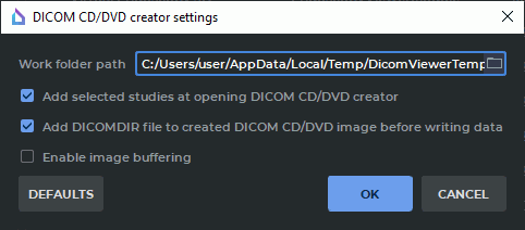
16.7.7 Set Up "DICOM CD/DVD Creator"
Select the DICOM CD/DVD creator module from the Installed modules and click the SETTINGS button. In the dialog box (Fig. 16.5), you can configure the following parameters:
-
The path to the working directory where the disk image aimed for recording is stored. By default, the working directory is in the OS temporary folder. You cannot provide an empty path to the working directory. If a path to a new working directory has been specified, but the old directory is not empty, a warning will be displayed;
-
the "Add selected studies at opening DICOM CD/DVD creator" option can be checked/unchecked;
-
the "Add DICOMDIR file to created DICOM CD/DVD image before writing data" option can be checked/unchecked;
-
the "Enable image buffering" option can be checked/unchecked.
16.7.8 Set Up Series fusion Module
Select the Series fusion module from the Installed modules and click the SETTINGS button.
The Controllers tab is used to customize the actions performed by the mouse.
16.7.9 Set Up PET Analysis Module
Select the PET Analysis module from Installed modules and click the SETTINGS button. You can specify the following parameters:
The Common tab:
-
Enable SUV mode automatically;
-
MIP layer CLUT by default;
-
window upper limit. The Max SUV value and Max window persent items are available;
-
First layer modality by default for the PET+CT window;
-
PET layer CLUT by default for the PET+CT window;
-
CT layer opacity (%) by default for the PET+CT window;
-
PET layer opacity (%) by default for the PET+CT window;
-
option Ask before deleting all annotations and measurements can be checked/unchecked.
In the Controllers MIP tab you can associate tools with the mouse wheel and move operations for the MIP window, in the Controllers 2D tab you can do it for the CT and PET windows. For details see Section 16.7.10.
The settings are applied the next time you open the PET Analysis window.
To restore default values, click the DEFAULTS button.
16.7.10 Mouse Settings
In the Controllers tab of the Image viewer, 3D reconstruction, Vessel analysis and PET analysis modules’ customization window, the user may assign the operations performed by default in the respective tabs to the mouse buttons, wheel and movements.
In the Mouse wheel operations section, you can set up the operations performed by default when the mouse wheel is rotated (with or without a modifier key).
To enable the selected operation, check the respective option in the Enabled column. If required, choose a modifier key for the selected operation on the drop-down list in the Modifier column.
In the Mouse keys operations section, you can set up the operations performed by default when you press a certain mouse key (with or without a modifier key).
To assign the selected operation to a mouse key, select it on the drop-down menu in the Pressed buttons column. If required, choose a modifier key for the selected operation on the drop-down list in the Modifier column.
If the selected combination already exists, the identical lines are highlighted with red.
| | The operations assigned to the mouse keys and wheel are applied by default only in the windows of the tab corresponding to the module being set up. |
If you activate a tool on the DICOM Viewer toolbar with a mouse button, the operation assigned to the button by default will be ignored. This operation will be performed by the mouse button only after the tool is deactivated.