6.10. Building Mask with Contours
____________________________________________________________________________________________
Functionality is available in the Pro edition
____________________________________________________________________________________________
6.10.1 General Information
Contours are used for segmentation of the organs whose density is comparable with the density of the surrounding tissue, e.g the heart, the liver, and joints. In such cases, it is hard to see the boundaries of the region. Hence, the automatic segmentation procedure cannot be applied.
Contours are built on sections in the MPR reconstruction tab. If the 3D view window is opened in the tab, the structure mask created is simultaneously shown on the volume model.
To customize the contours display, click the arrow on the right-hand side of the Contour
segmentation  button and provide the required parameters in the menu.
-
To enable/disable the contours display on the volume model, check/uncheck the box next to the Show contours in 3D option. By default, the option is enabled.
-
To enable/disable the synchronization point display when the user hovers over the contour, check/uncheck the box next to the Show syncpoint option. By default, the option is disabled.
-
to enable/disable automatic rebuilding of a structure mask in alignment with the contours, check/uncheck the Interactive voxelization box. By default, this option is enabled. If the interactive voxelization option is disabled, use the Voxelize unction on the tool context menu to rebuild the mask manually. For details, see Section 6.10.3.
6.10.2 Building a Structure Mask with Contours
To build a structure mask with contours, proceed as follows:
-
Open the study in the MPR Reconstruction tab. Create a structure with an empty mask and configure the editing mask by setting the tissue density. For the details on editing mask creation, see Section 6.2.1.
-
Activate the Contour segmentation
tool by clicking the left/right/middle mouse
button. To continue work with this tool, use the button with which the tool was activated.
To learn more about tool control, see Section 1.14. Build the contour in one of the
following ways:
-
Building contours manually. Build a contour around the chosen area while holding the mouse button with which the tool was activated. To finish the procedure, release the mouse button. To cancel the contour that has not been closed, press Esc on the keyboard while holding the button.
-
Building contours with an isoline. Move the cursor around the selected area while holding the Shift button on the keyboard. Under the cursor, you will see an isoline characterized by even points density. You can only see an isoline on the surfaces where a contour can be built. To build a contour with an isoline, click the left mouse button or the mouse button with which the tool was activated.
-
-
Go to the next slice and draw a contour around the selected area. Contours are only built on parallel planes. Contours are used to create a mask with regard for the editing mask. You need at least two contours to build a structure mask.
Structure mask may not be shown on the sections with the first and the last contour.
Building contours automatically with segmented structure sections. Contours are built on the current section of the structure mask. The structure mask on which contours are built may be built with any tools. The following conditions must be met in order to build a contour on a structure mask:
-
the current section must be placed in parallel with other contours;
-
there must be no other contours of the same structure mask on the current section;
-
the structure mask must be visible on the current section.
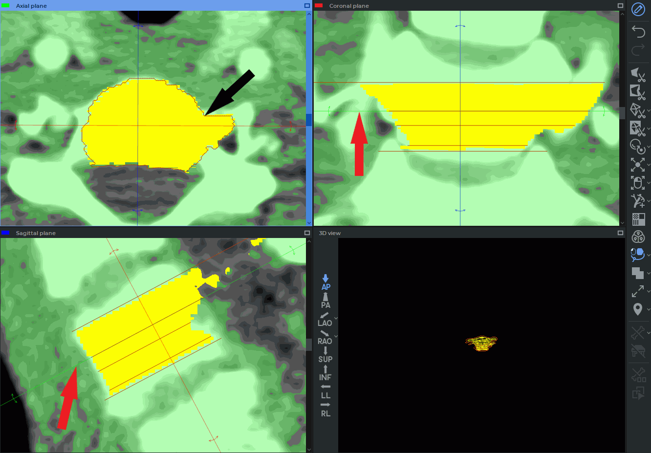
Mouse over a section parallel to the structure mask contours. The mask should be visible in the current slice. Click the right mouse button and select the Create contour X option from the menu, or press X on the keyboard. The contour will be built on the current section (indicated by the red arrow in the fig. 6.31) around the perimeter of the visible part of the current structure mask (indicated by the black arrow in the fig. 6.31). If a contour (or several contours) already exists on the current section, no other contour will be built.
To undo an action, click the Undo  button, to repeat the canceled action, click the Redo
 button. You can use the Undo and Redo buttons to delete or restore the contours that were
built in one click.
button. You can use the Undo and Redo buttons to delete or restore the contours that were
built in one click.
Contours projections are shown on perpendicular sections of the MPR reconstruction tab, in the 3D view window and on the sections where they were built. If a slice is not perpendicular to the contour plane, the projection of this contour is not shown.
When you hover over the contour line, it is highlighted in all the windows of the tab.
If the Show syncpoint option is enabled and the user hovers over the contour in any of the cutting plane windows or in the 3D view window, the crosshair under the cursor and the synchronized crosshairs on the contours in other windows of the tab are displayed.
If you click the mouse button while the cursor is on the contour line in the 3D view window, you will go to the section with this contour in the MPR reconstruction window.
6.10.3 Work with Contours
DICOM Viewer provides for the following actions with contours:
-
Editing. To edit a contour, place the cursor over it. When you hover over the contour line, it is highlighted in all the windows of the tab. Place the cursor over the area that needs editing and click the mouse button. Draw a new contour while holding the button. To finish the editing procedure, release the mouse button. To undo an action, click the Undo
button, to repeat the canceled action, click the Redo button. You
can use the Undo and Redo buttons to delete or restore the parts of the contour that
were built in one click (from the moment you press the mouse button to the moment the
button is released);
-
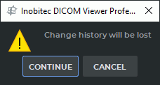
Rebuilding a mask manually. This function is used when the automatic structure mask rebuilding function is disabled in the Contour segmentation button menu. To do it, you need to mouse over the contour line, click the right mouse button and choose the Voxelize option on the context menu. If the contour is built for a structure mask created with the help of other tools, you will not be able to undo an action after voxelization. Before voxelization is performed, a dialog box pops up informing you that the change history will be lost (Fig. 6.10.3);
To accept the changes, click the CONTINUE button. To cancel voxelization, click the CANCEL button.
-
Deleting. Place the cursor over the contour line, press the Delete key on the keyboard or click the right mouse button and choose the Remove contour option in the right-click menu. To undo an action, click the Undo
button, to repeat the canceled action, click the Redo
button. You can use the Undo and Redo buttons to delete or restore the parts of the
contour that were built in one click (from the moment you press the mouse button to the
moment the button is released).
6.10.4 Setting the Contour Display Parameters
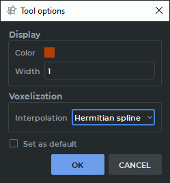
You can customize the contour display parameters in the Tool options dialog box (Fig. 6.33). The appearance and the functions of the Tool options dialog box depend on the way you call for it. There are two ways to call for the Tool Options dialog box:
-
Place the cursor over the contour line, click the right mouse button and choose the Tool options... point in the right-click menu. The dialog shown in Fig. 6.33a appears.
-
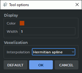
On the volume editing panel, click the arrow on the right-hand side of the Contour segmentation
button and select Default options... from the button menu.
The dialog shown in Fig. 6.33b appears.
In the dialog box that pops up (see Fig. 6.33), in the Display section select the color and the contour line thickness in pixels. From the Interpolation drop-down list in the Voxelization section, select the interpolation type for the segmented structure built with contours. The interpolation types available are:
-
-
Linear;
-
Hermitian spline (set by default).
The interpolation type chosen will be displayed next time you open the structure selection dialog box.
The parameters selected in the dialog box Fig. 6.33a will be applied to the contours of the current structure mask. If you check the Set as default box, the settings will be used by default when building the contours of a new structure mask.
The parameters set in the dialog box shown in Fig. 6.33b are applied by default to the Contour segmentation tool. The changes are not applied to the built contours of masks. To restore the initial tool parameters, click the DEFAULT button.
Click OK to apply the settings or CANCEL to cancel.