6.5. Building surface
____________________________________________________________________________________________
Functionality is available in the Pro edition
____________________________________________________________________________________________
The DICOM Viewer allows you to create a surface for segmented structures and base volume in the Volume Reconstruction window and in the Multiplanar Reconstruction window. In multiphase series, you can build a surface for base volume of the each phase.
 | Attention! Surfaces transparency is not supported if:
|
| | On macOS 10.15 and later, it is recommended to use a visualization device that supports Metal polygonal and voxel rendering. The settings are described in Section 16.7.3. |
On the segmented structures list, select the base volume or the structure for which you want to build a surface.
To customize the parameters used by default when building a surface, click the Parameters
 button on the segmented structures panel and select the Default surface parameters...
option. In the dialog box that pops up (Fig. 6.11), provide the required default parameters for
building surfaces.
button on the segmented structures panel and select the Default surface parameters...
option. In the dialog box that pops up (Fig. 6.11), provide the required default parameters for
building surfaces.
To build a surface, click on the Create surface for current structure  button on the
segmented structures list. The surface is built according to the current settings.
button on the
segmented structures list. The surface is built according to the current settings.
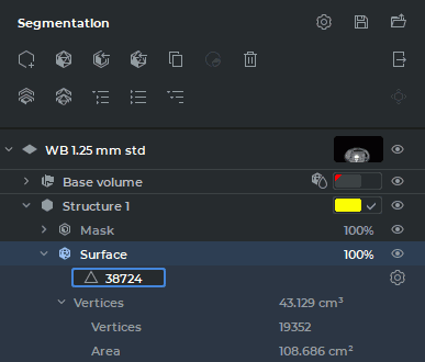
To customize the parameters for each of the surfaces built, unfold the surface properties tree on
the segmented structure panel (see Fig. 6.10). Click the Change surface creation
parameters button.
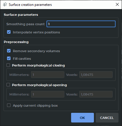
Set the surface parameters in the dialog box that pops up (see Fig. 6.11).
-
The smoothness of the surface is defined by the Smoothing pass count parameter. With this parameter set at zero value, the form of the surface is as close as possible to the structure. With an increase in the value, the surface roughness disappears.
-
If the Interpolate vertex positions box is checked (checked by default), the surface is smoothed at the border of the volume.
-
To create the surface only for the largest structure, check the Remove secondary volumes box.
-
To fill the cavities and hollows, check the Fill cavities. box. As an alternative, you can use the
 Fill tool (see Section 3.8.7).
-
To fill small cavities, check the Perform morphological closing box. As an alternative, you can use the
 Remove holes (closing) tool (see Section 3.8.7). The volume
of the model is first increased and then decreased by the operation radius provided (in
millimeters or voxels). The shape of the surface and the external dimensions are not
changed.
Remove holes (closing) tool (see Section 3.8.7). The volume
of the model is first increased and then decreased by the operation radius provided (in
millimeters or voxels). The shape of the surface and the external dimensions are not
changed.
-
To eliminate visual surface defects, check the Perform morphological opening box. As an alternative, you can use the
 Remove noise (opening) tool (see Section 3.8.7).
The volume of the model is first decreased and then increased by the operation radius
provided (in millimeters or voxels). The shape of the surface and the external dimensions
are not changed.
Remove noise (opening) tool (see Section 3.8.7).
The volume of the model is first decreased and then increased by the operation radius
provided (in millimeters or voxels). The shape of the surface and the external dimensions
are not changed.
-
If the Apply current clipping box box is checked, then the surface is built only for that part of the structure which is inside the cube.
To apply the settings, click OK. To cancel, click CANCEL.
When the segmentation project is saved, all the surface building parameters are saved in the file. For details on saving projects, see Section 6.11.
The surface is represented by a polygon model made of triangles.
The program automatically determines the maximum possible number of triangles required for creating a surface imitating the volume surface. The number of the triangles making up the surface may be changed on the Segmented structure panel.
To change the number of the triangles making up the surface, unfold the surface properties tree on the Segmented structure panel (Figure 6.10).
Double-click with the left mouse button on the value in the field with a triangle icon. Change the value showing the number of triangles and press Enter key on the keyboard.
If the number of triangles entered is too small or too large to build a surface, the DICOM Viewer will use the value from the permitted range which is the closest to the value provided by the user.
If the entered value equals 0, the program will build a surface using the maximum possible number of triangles which will be shown in the field with a triangle icon.
If visibility for this structure or surface is disabled, you cannot use the cutting tools, as well as the Segmentation from point by mask, Region growing and Vessel tree segmentation tools.
You can only edit hidden structures with intelligent volume editing tools, such as Grow (dilation), Shrink (erosion), Remove noise (opening), Remove holes (closing) (for details see Section 3.8.7) , as well as with the Union, Subtract, Subtract dilated, and Intersect tools (for details see Section 6.9). In this case, the following message pops up: "The target structure is hidden. Are you sure you want to apply the operation to it?" Click Yes to proceed or No to cancel.