5.5 Working with Orthogonal Planes
5.5.1 View Modes
Click the Switch navigation mode button and select one of the three view modes:
-
The 3D cursor mode. It allows you to drag and rotate orthogonal cutting planes using
the mouse. The Switch navigation mode button will look as follows:  .
.
-
The on click 3D cursor mode. It allows you to move orthogonal cutting planes similarly
to the 3D cursor mode, but the plane lines are visible only during the dragging (while
the left mouse button is pressed). The Switch navigation mode button will look as
follows:  .
.
-
The planes cursor mode. The cutting planes are displayed permanently. Their moving is
described in the next section. The rotation of planes is similar to the 3D cursor mode and
is described in Section 5.5.2. The Switch navigation mode button will look as follows:
 .
.
In all the view modes the current plane can be moved in several ways:
-
scroll the mouse wheel. If you scroll the wheel forward, the plane will withdraw, if you
scroll it backward, the plane will move nearer. One click of the mouse wheel changes the
plane position by the distance equal to the thickness of the slice from the initial series;
-
by use the scrollbar on the right side of the section view window to move the section;
-
use the  Scrolling tool. Activate the tool on the toolbar by clicking the
left/right/middle mouse button and move the cursor up to withdraw the plane or down
to move it nearer, holding down the button with which the tool was activated. To learn
more about tool control, see Section 1.14.
Scrolling tool. Activate the tool on the toolbar by clicking the
left/right/middle mouse button and move the cursor up to withdraw the plane or down
to move it nearer, holding down the button with which the tool was activated. To learn
more about tool control, see Section 1.14.
5.5.2 Working with Planes in 3D Cursor Mode
To move orthogonal planes, click the left mouse button at the point you want to move the planes to,
or move the mouse, holding the left button. When the button is released, the position of the planes is
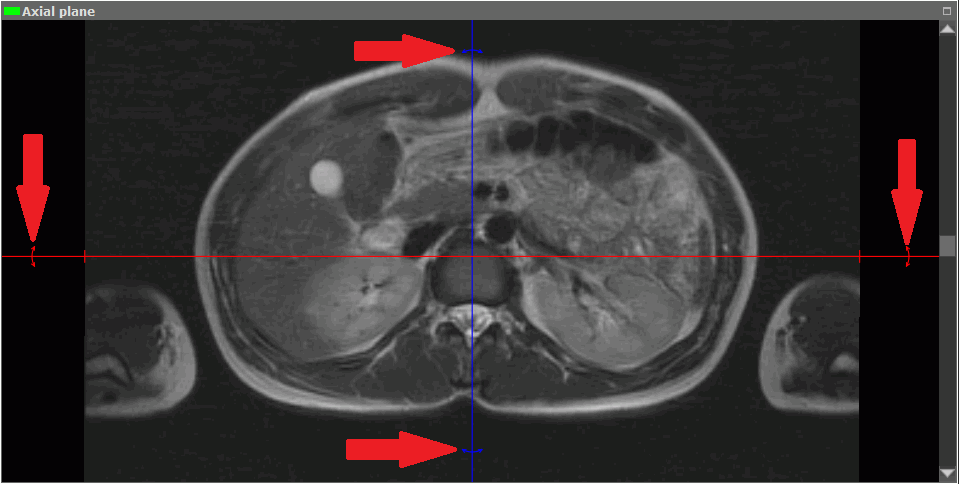
fixed. To rotate a plane while maintaining orthogonality:
-
Locate the cursor on the radial bidirectional arrow on the plane line (see red arrows in
Fig. 5.6). The bidirectional arrow will be highlighted.
-
Move the cursor, holding the left mouse button to rotate the plane by the required angle.
The images on the other planes will change.
-
Release the left mouse button to fix the current position of the plane.
To rotate a plane without maintaining orthogonality, follow the steps above, holding the Shift key
while performing the step 2.
To undo the rotation of all planes, click the Undo rotation button on the toolbar  .
.
 | Note
that
all
the
other
view
changes
will
be
undone
as
well. |
5.5.3 Working with Planes in the Cutting Plane Mode
The DICOM Viewer allows you to move planes one by one in the image view modes. To do
this:
-
Locate the cursor on the plane line to highlight it.
-
Move the line, holding the left mouse button.
Scroll the images in some window to see how the target plane is moving in the other
windows.
For convenience, zoom the image in and out by rolling the mouse wheel, holding the Ctrl key (or
the Command key for macOS).
There are two ways to move images in the window for viewing cutting planes:
-
Move the mouse holding the wheel and the "Shift" key on the keyboard. This key
combination is set by default. You can disable or change the setting in the Controllers
tab of the Image viewer module (see Section 16.7.1).
-
Activate the Pan  tool on the toolbar by clicking the left/right/middle mouse button.
To continue work with this tool, use the button with which the tool was activated.To learn
more about tool control, see Section 1.14. To move an image, move the cursor around
the screen while holding down the mouse button.
tool on the toolbar by clicking the left/right/middle mouse button.
To continue work with this tool, use the button with which the tool was activated.To learn
more about tool control, see Section 1.14. To move an image, move the cursor around
the screen while holding down the mouse button.
This tool is also available from the image context menu and from the MPR main menu
item.