5.6 Series Synchronization in MPR Reconstruction Tabs
Series synchronization is used for viewing series of one or several studies simultaneously. The
opportunity to compare series created at different times allows the user to evaluate the
changes and improves diagnostic accuracy. Series can be compared in MPR reconstruction
tabs.
To compare series, open them in MPR reconstruction tabs. The tabs may:
-
be placed in the main program window or be unattached to it;
-
be placed on the same or on different monitor screens. The monitors may be different in
size and have different settings (e.g. scaling, resolution, brightness, contrast etc.).
To enable synchronization, click the Sync series  button. Synchronization provides the user
an opportunity to change window width and level (W/L) settings, move, scale and scroll images from
different series in section plane windows. Synchronization is disabled by default. If synchronization is
enabled and the user opens a new tab, the new tab will be synchronized with the one that was opened
earlier.
button. Synchronization provides the user
an opportunity to change window width and level (W/L) settings, move, scale and scroll images from
different series in section plane windows. Synchronization is disabled by default. If synchronization is
enabled and the user opens a new tab, the new tab will be synchronized with the one that was opened
earlier.
To set synchronization types and modes, proceed as follows:
-
Click the arrow on the Sync series button on the toolbar.
-
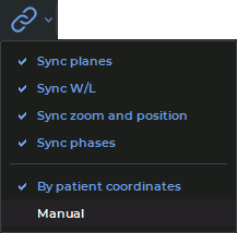
Select the synchronization types and modes from the drop-down menu (Fig. 5.7):
-
Sync planes. Planes and rotation angles of orthogonal planes are synchronized in MPR
reconstruction tab windows (Axial plane, Coronal plane and Sagittal plane). Other
MPR reconstruction tab windows are not synchronized;
-
in the By patient coordinates mode, synchronization is only performed
for series with the same frameOfReferenceUid tag value. If synchronization is
enabled, the orthogonal planes of the new tab are synchronized with the planes
of the tab that was opened earlier;
-
in the Manual mode, synchronization is performed for series with different
frameOfReferenceUid tag values. In this case, the same changes regarding
scrolling the synchronized and the synchronizing viewer window will be applied
in the patient’s coordinate system. Planes in synchronized windows will be
turned around the line of intersection of orthogonal planes through the same
angle;
-
Sync W/L. Changes in the window width and level (W/L) will be synchronized for
series with the CT modality. For series with other modalities, synchronization
will only be performed if the modalities of the series and the recommended
width and level (W/L) values are the same. Series with different modalities
cannot be synchronized. The chosen mode has no impact on this synchronization
type.
If synchronization has been enabled, the window width and level (W/L) values of
the tab opened will be synchronized with those of the tab that was opened
earlier.
Merged series are synchronized layer by layer. Layers are synchronized by their respective
numbers (the first layer is synchronized with the first one, the second layer is synchronized
with the second one etc.);
-
Sync zoom and position. The scaling and position changes are synchronized in MPR
reconstruction tab windows (Axial plane, Coronal plane, and Sagittal plane). Other
MPR reconstruction tab windows are not synchronized. Merged series are synchronized
on the basis of the data for the first layers of the series. This synchronization type
functions differently depending on the mode chosen.
-
Sync phases. The image phases are synchronized by number. If the phase number
for the synchronizing series is greater than the total number of phases in the
synchronized series, then the phase with the greatest number will be selected for the
synchronized series. This synchronization type does not depend on the chosen
mode.