button on the segmented structures
panel and select the Export/Import parameters... option. In the dialog box that pops up
(Fig. 6.14), provide the parameters for exporting.
button on the segmented structures
panel and select the Export/Import parameters... option. In the dialog box that pops up
(Fig. 6.14), provide the parameters for exporting.
____________________________________________________________________________________________
Functionality is available in the Pro edition
____________________________________________________________________________________________
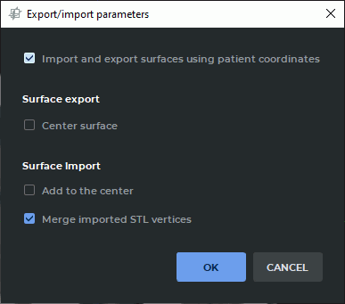
To customize export parameters, click the Parameters button on the segmented structures
panel and select the Export/Import parameters... option. In the dialog box that pops up
(Fig. 6.14), provide the parameters for exporting.
to move the reference point (the point relative to which the model can be deformed in the Vector graphics editors) to the geometrical center of the surface, in the dialog box check the Center surface box. The option is disabled by default;
to use the patient’s coordinates when exporting, check the Import and export surfaces using patient coordinates box. Coordinates for markers are exported in the same coordinate system as the surface coordinates. Check box is set by default;
choose the measurement units for the coordinates. This setting has impact on the surface and markers export. Millimeters are chosen by default. If meters are used, the values of the exported coordinates are divided by 1000;
in the Markers section, select the type of exported markers from the list. By default, all the types are selected. If the information on the markers is exported in a .csv file, check the boxes for the additional marker fields to be exported (text, marker size and color).
To apply the settings, click OK. To cancel, click CANCEL.
____________________________________________________________________________________________
Functionality is available in the Pro edition
____________________________________________________________________________________________
Surface export parameters can be customized in the Export/import parameters dialog box (see Section 6.7.1).
To export a segmented structure surface, proceed as follows:
On the segmented structures panel, select the surface to be exported.
Call up the popup menu with the export options in one of the following ways:
click the Export  button on the segmented structures panel and choose the
type of export from the popup menu;
button on the segmented structures panel and choose the
type of export from the popup menu;
mouse over the structure on the list, right-click and choose the Export option from the right-click menu. Then select the type of export.
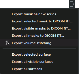
There are three options for exporting a surface:
Export selected surface. Only the surface that is currently chosen is exported. It may be exported in .ply, .obj, .stl or .glb format. In the dialog box that appears, select the file type and save the surface;
Export all visible surfaces. All the visible surfaces for which visibility in the segmented structures panel is enabled are exported. They may only be exported in .glb format;
Export all surfaces. All the surfaces on the segmented structure panel are exported. They may only be exported in .glb format.
If export is performed for several layers, the hierarchy is retained: layers (with the name of the respective series) occupy the first level, while the second level is occupied by surfaces. When surfaces are exported from the same layer, only one hierarchy level (surfaces) is retained.
The name, the color of the apices and the transparency are retained for each surface. When several surfaces are exported, their relative position which is the same as the relative position in the DICOM Viewer at the time of export is retained.
 | You need to be aware that when the surface is printed by a 3D printer,
errors may occur for the following reasons:
|
____________________________________________________________________________________________
Functionality is available in the Pro edition
____________________________________________________________________________________________
To customize import parameters, click the Parameters button on the segmented structures
panel and select the Export/Import parameters... option. In the dialog box that pops up
(Fig. 6.16), check the following boxes:
to use the patient’s coordinates, check the Import and export surfaces using patient coordinates box. Coordinates for markers are imported in the same coordinate system as the surface coordinates;
choose the measurement units for the coordinates. This setting has impact on the surface and markers import. Millimeters are chosen by default. If meters are used, the values of the imported coordinates are divided by 1000;
to align the centers of the imported surface and the model when importing, check the Add to the center box;
to merge the vertices of the triangles when importing a surface in (stl) format, check the Merge imported STL vertices box. This box is checked by default;
in the Markers section, select the type of imported markers from the list. By default, all the types are selected. If the information on the markers is imported from a .csv file, check the boxes for the additional marker fields to be imported (text, marker size and color).
Click OK to apply the settings or CANCEL to cancel.
____________________________________________________________________________________________
Functionality is available in the Pro edition
____________________________________________________________________________________________
Surface import parameters can be customized in the Export/import parameters dialog box (see Section 6.7.3).
Attention! When importing a surface, in the settings dialog box, specify the coordinates measurement units that were provided for export.
There are two ways to import surfaces:
click the Import surface(s)  button. In the dialog box that pops up, select the
files and click Open;
button. In the dialog box that pops up, select the
files and click Open;
mouse over the structure on the list, right-click and choose the Import->Import surface(s)... option from the right-click menu. In the dialog box that pops up, select the files and click Open.
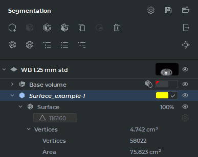
The name of the imported surface, as well as the name of any structure without a structure mask, is shown in italics. In Figure 6.17 you see an imported surface Surface_example-1. You cannot change the number of triangles for the imported surface.
To move the imported surface manually, activate the tool Surface positioning  by clicking
the left/right/middle mouse button. To continue work with this tool, use the button with
which the tool was activated. To learn more about tool control, see Section 1.14. Move the
surface on the plane of the screen, holding the mouse button with which the tool was
activated.
by clicking
the left/right/middle mouse button. To continue work with this tool, use the button with
which the tool was activated. To learn more about tool control, see Section 1.14. Move the
surface on the plane of the screen, holding the mouse button with which the tool was
activated.
To scale the surface, move the mouse up and down while holding the Ctrl key (or the Command key for macOS) and the button with which the tool was activated.
To rotate the surface around its center, move the mouse while holding the Alt key (or the Option key for macOS) and the button with which the tool was activated.
To create a segmented structure for a surface, place the cursor over the copy of the surface, click the right mouse button and choose the Create mask by surface point in the right-click menu.
____________________________________________________________________________________________
Functionality is available in a separate module which is activated in the Pro edition for an extra fee
____________________________________________________________________________________________
The DICOM Viewer allows for exporting masks of segmented structures to the current study as a new series or as DICOM RT Structure Set IOD.
To export a structure mask to the current study as a new series, proceed as follows:
Select the structure mask you need on the Segmented structure panel.
Export the structure mask to the current study in one of the following ways:
click the Export button on the segmented structures panel and choose the
Export mask as new series option from the popup menu;
mouse over the structure on the list, whose mask you want to export right-click and choose the Export option from the right-click menu. Then select the Export mask as new series option.
The exported structure mask will be saved in the local storage as a new series of the current study. A thumbnail for the new series will be added to the series panel.
The structure mask of the selected layer is exported in the coordinate system of the basic layer series with consideration to level-to-level fusion. The FrameOfReferenceUID tag value for the exported series is the same as the FrameOfReferenceUID tag value for the basic layer.
The exported structure mask can be opened in the flat image viewer, volume reconstruction, or MPR reconstruction tab.
The position of slices in a new series is in compliance with the window that was selected when the Export mask as new series command was given. If a 3D view window is selected, then the position of the planes will be in compliance with the position of the slices in the Axial plane window.
____________________________________________________________________________________________
Functionality is available in a separate module which is activated in the Pro edition for an extra fee
____________________________________________________________________________________________
To export a structure mask of the segmented structure to DICOM RT, proceed as follows:
On the segmented structures panel, select the structure whose mask to be exported to DICOM RT.
Call up the popup menu with the export options (Fig. 6.18) in one of the following ways:
click the Export button on the segmented structures panel and choose the
type of export to DICOM RT from the popup menu;
mouse over the structure on the list whose mask you want to export, right-click and choose the Export option from the right-click menu. Then select the type of export to DICOM RT.
There are three ways to export a mask of structure to DICOM RT:
Export selected mask to DICOM RT.... Only the mask of the currently selected structure is exported;
Export visible masks to DICOM RT.... All the visible masks of structures from the segmented structures panel (for which the visibility button has been activated) are exported;
Export all masks to DICOM RT.... All the masks of structures structures from the segmented structures panel are exported.
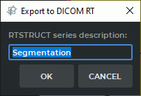
In the Export to DICOM RT (Fig. 6.19) dialog box that pops up, add a description of the exported RTSTRUCT series. The default series description is "Segmentation".
Click OK button to export mask of structure or CANCEL to cancel.
The exported mask of structure will be saved in the local storage as a new series with RTSTRUCT modality. A thumbnail for the new series will be added to the series panel.
If a series has several phases, the mask of structure will only be exported for the current phase. If no mask was exported during the export procedure (e.g. no voxels are visible under the editing mask), an error message will pop up.
____________________________________________________________________________________________
Functionality is available in a separate module which is activated in the Pro edition for an extra fee
____________________________________________________________________________________________
There are two ways to import a mask of segmented structure from DICOM RT:
click the Import masks from DICOM RT...  button on the segmented structures
panel;
button on the segmented structures
panel;
mouse over the structure on the list, whose mask you want to import right-click and choose the Import option from the right-click menu. Then select the Import masks from DICOM RT... option.
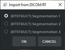
In the Import from DICOM RT dialog box (Figure 6.20), select an RTSTRUCT modality series to import.
Click OK button to import structure mask or CANCEL to cancel.
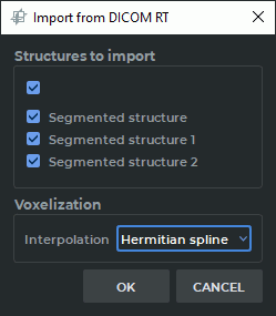
In the Structures to import section of the dialog box (Figure 6.21), check the box next to the structure whose mask you want to import. To import all the masks of the structures from the list, check the upper box. By default, the boxes are not checked.
Click OK to import structure mask or CANCEL to cancel.
____________________________________________________________________________________________
Functionality is available in a separate module which is activated in the Pro edition for an extra fee
____________________________________________________________________________________________
The DICOM Viewer provides an opportunity to export information on markers and segmented structure markers in .csv and .json files.
For details on markers, see Section 5.12, on segmented structure markers — Section 6.8.5.
To export markers, proceed as follows:
Customize the parameters for markers export in the Export/import parameters dialog box (see Section 6.7.1).
 | When markers are exported in .json format, in the settings dialog box, check or uncheck the box enabling the use of patient coordinates, specify the coordinates measurement units and the type of markers to be exported. When markers are exported in .csv format, check or uncheck the box enabling the use of patient coordinates and specify the coordinates measurement units, marker parameters (text, size and color) and the type of markers to be exported |
Depending on the selected marker type, the size in export files is specified as the marker radius in millimeters or the line thickness in pixels.
Click the Export button on the segmented structures panel.
Select the Export markers... option on the drop-down menu. If there are no markers of the type specified in the export settings dialog box, the option is unavailable (see Section 6.7.1).
In the dialog box that pops up, select the directory where the file is to be saved. Edit the file name and select the file type: .csv or .json. Click Save to save or Cancel to cancel.
The markers exported from a model created for a fused series are exported to .csv or .json files with the basic layer coordinates.
To export segment markers, proceed as follows:
On the segmented structures panel, right-click on the structure the markers from which are to be exported.
Select Export -> Export markers... from the context menu. If there are no segmented structure markers on the selected structure, the option will be unavailable.
| | When segmented structure markers are exported, in the export settings dialog box, check or uncheck the box enabling the use of patient coordinates and specify the coordinates measurement units. Only the coordinates for segment markers with the characteristics specified in the settings dialog box will be exported to .json or .csv format. |
In the dialog box that pops up, select the directory where the file is to be saved. Edit the file name and select the file type: .csv or .json. Click Save to save or Cancel to cancel.
____________________________________________________________________________________________
Functionality is available in a separate module which is activated in the Pro edition for an extra fee
____________________________________________________________________________________________
The DICOM Viewer provides an opportunity to import information on markers and segmented structure markers from .csv and .json.
To import markers, proceed as follows:
Customize the parameters for markers import in the Export/import parameters dialog box (see Section 6.7.3).
| | When markers are imported from a .csv file, in the settings dialog box, check or uncheck the box enabling the use of patient coordinates and specify the coordinates measurement units, marker parameters (text, size and color), and the type of markers (the parameters that were specified for export). If there are additional marker parameters in the imported file or if some parameters are missing, the import operation is interrupted. When markers are imported from a .json file, check or uncheck the box enabling the use of patient coordinates and specify the coordinates measurement units that were provided for export. |
Right-click on the base volume or on its child element on the segmented structures panel. Then select Import -> Import markers... from the context menu.
In the dialog box that pops up, select the file to be imported. Click Open to import or Cancel to cancel.
The markers exported from a model for a fused series cannot be imported back to the layers from which they were exported. When imported from a .json file to a selected layer, the coordinates of markers from other layers are transformed in compliance with the transformation matrix for the selected layer. If the user attempts to import markers to a layer with no transformation matrix, a warning will pop up informing that this procedure is invalid. When markers from a .csv file are imported to a selected layer, their coordinates are not transformed.
| | When importing markers for a fused series from a .csv file, the user must be absolutely sure that the layer has been chosen correctly and that the systems of reference are the same. |
To import segment markers, proceed as follows:
On the segmented structures panel, right-click on the selected segmented structure list item and choose Import -> Import markers... from the context menu.
| | When segmented structure markers are imported, in the import settings dialog box, check or uncheck the box enabling the use of patient coordinates and specify the coordinates measurement units that were provided for export. Only coordinates for segmented structure markers can be imported from .json or .csv files. |
In the dialog box that pops up, select the file to be imported. Click Open to import or Cancel to cancel.