| Color tables are needed for displaying pixels and voxels representing different density values in different colors for improved perception. The shades on the screen are different from the real shades. |
____________________________________________________________________________________________
Functionality is available in a separate module which is activated in the Pro edition for an extra fee
____________________________________________________________________________________________
| | Color tables are needed for displaying pixels and voxels representing different density values in different colors for improved perception. The shades on the screen are different from the real shades. |
Image visualization is described in Section 2.23. To change the CLUT for a specific window, first select this window with a mouse click. In the PET+CT window you can change the CLUT for the PET layer only.
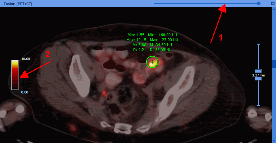
To change the PET layer opacity in the PET+CT window, move the slider at the top of the PET+CT window (marked with number "1" in Fig. 9.5).
The PET+CT window contains the scale of the CLUT for the PET layer (marked with number "2" in Fig. 9.5). If the SUV mode is disabled, the scale borders coincide with the minimum and maximum window values for the PET layer. If the SUV mode is enabled, then the scale borders coincide with the minimum and maximum values of the SUV in the current image of the PET layer.
Changing the window width and the window level using the Adjust W/L  tool is described
in 2.17. To change the window width and the window level for CT images in the CT and PET+CT
windows, select the CT window with the mouse. To change the values for all PET images, select any
window with the mouse, except for the CT window.
tool is described
in 2.17. To change the window width and the window level for CT images in the CT and PET+CT
windows, select the CT window with the mouse. To change the values for all PET images, select any
window with the mouse, except for the CT window.
 | Attention! You can change only the upper window limit in the PET+CT and PET windows for the PET layer, using the "Adjust W/L" tool. |
The default upper window level value is determined by the Window upper limit setting. There are two ways to adjust the upper limit:
Max SUV value. In this case, the default window upper limit is set equal to the corresponding value in the SUV mode.
Max window percent. In this case, the default window upper limit is set equal to the specified percentage of the recommended window width. Since the default lower limit for PET is zero, the window width is numerically equal to the upper limit, and the percentage is actually calculated from its value. If different recommended upper limits are set for different images of the series, then the percentage is calculated from the maximum of these values.